Panasonic 26PEF1U6 26PEU1U6 Owner's Manual - Page 6

Contents, Outdoor Unit Maintenance Remote Control

Page 6 highlights

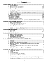
Contents Section 1: SPECIFICATIONS...1-1 1-1 Unit SpecifIcations 1-2 1-2 Major Component SpecifIcations 1-20 1-3 Other Component SpecifIcations 1-35 1-4 Dimensional Data 1-38 1-5 Refrigerant Flow Diagram 1-48 1-6 Operating Range 1-49 1-7 Capacity Correction Graph According to Temperature Condition 1-50 1-8 Noise Criterion Curves 1-51 1-9 Increasing the Fan Speed 1-56 1-10 Air throw distance chart 1-57 1-11 ELECTRICAL WIRING 1-60 1-12 Installation Instructions 1-63 1-13 HOW TO PROCESS TUBING 1-118 1-14 LEAK TEST, EVACUATION AND ADDITIONAL REFRIGERANT CHARGE .... 1-122 Section 2: PROCESSES AND FUNCTIONS 2-1 2-1 Room Temperature Control 2-2 2-2 Cold Draft Prevention (Heating Cycle 2-4 2-3 Automatic Fan Speed (Indoor Unit 2-5 2-4 Control Functions 2-6 2-5 Outdoor Unit Control PCB 2-9 2-6 Outdoor Unit Control PCB (CR-CH4272R 2-10 Section 3: ELECTRICAL DATA 3-1 3-1 Indoor Units ...3-2 3-2 Outdoor Units...3-10 Section 4: SERVICE PROCEDURES 4-1 4-1 Meaning of Alarm Messages 4-2 4-2 Symptoms and Parts to Inspect 4-5 4-3 Details of Alarm Messages 4-8 4-4 Table of Thermistor Characteristics 4-14 Section 5: OUTDOOR UNIT MAINTENANCE REMOTE CONTROL 5-1 5-1 Overview ...5-2 5-2 Functions ...5-2 5-3 Normal Display Operations and Functions 5-3 5-4 Monitoring Operations: Display of Indoor Unit and Outdoor Unit Sensor Temperatures ...5-6 5-5 Monitoring the Outdoor Unit Alarm History: Display of Outdoor Unit Alarm History ...5-7 5-6 Setting Modes: Setting the Outdoor Unit EEPROM 5-7 Section 6: TSET RUN...6-1 6-1 Preparing for Test Run 6-2 6-2 Caution ...6-3 6-3 Test Run Procedure 6-3 6-4 Items to Check Before the Test Run 6-4 6-5 Test Run Using the Remote Controller 6-4 6-6 Precautions ...6-4 6-7 Table of Self-Diagnostic Functions and Corrections (U1, K1, T1, F1 Type) ........ 6-5 6-8 Examples of Wiring Diagrams 6-6 vi

  • 1
  • 2
  • 3
  • 4
  • 5
  • 6
  • 7
  • 8
  • 9
  • 10
  • 11
  • 12
  • 13
  • 14
  • 15
  • 16
  • 17
  • 18
  • 19
  • 20
  • 21
  • 22
  • 23
  • 24
  • 25
  • 26
  • 27
  • 28
  • 29
  • 30
  • 31
  • 32
  • 33
  • 34
  • 35
  • 36
  • 37
  • 38
  • 39
  • 40
  • 41
  • 42
  • 43
  • 44
  • 45
  • 46
  • 47
  • 48
  • 49
  • 50
  • 51
  • 52
  • 53
  • 54
  • 55
  • 56
  • 57
  • 58
  • 59
  • 60
  • 61
  • 62
  • 63
  • 64
  • 65
  • 66
  • 67
  • 68
  • 69
  • 70
  • 71
  • 72
  • 73
  • 74
  • 75
  • 76
  • 77
  • 78
  • 79
  • 80
  • 81
  • 82
  • 83
  • 84
  • 85
  • 86
  • 87
  • 88
  • 89
  • 90
  • 91
  • 92
  • 93
  • 94
  • 95
  • 96
  • 97
  • 98
  • 99
  • 100
  • 101
  • 102
  • 103
  • 104
  • 105
  • 106
  • 107
  • 108
  • 109
  • 110
  • 111
  • 112
  • 113
  • 114
  • 115
  • 116
  • 117
  • 118
  • 119
  • 120
  • 121
  • 122
  • 123
  • 124
  • 125
  • 126
  • 127
  • 128
  • 129
  • 130
  • 131
  • 132
  • 133
  • 134
  • 135
  • 136
  • 137
  • 138
  • 139
  • 140
  • 141
  • 142
  • 143
  • 144
  • 145
  • 146
  • 147
  • 148
  • 149
  • 150
  • 151
  • 152
  • 153
  • 154
  • 155
  • 156
  • 157
  • 158
  • 159
  • 160
  • 161
  • 162
  • 163
  • 164
  • 165
  • 166
  • 167
  • 168
  • 169
  • 170
  • 171
  • 172
  • 173
  • 174
  • 175
  • 176
  • 177
  • 178
  • 179
  • 180
  • 181
  • 182
  • 183
  • 184
  • 185
  • 186
  • 187
  • 188
  • 189
  • 190
  • 191
  • 192
  • 193
  • 194
  • 195
  • 196
  • 197
  • 198

vi
Section 1: SPECIFICATIONS
.....................................................................................................
1-1
1-1 Unit SpecifIcations
..............................................................................................
1-2
1-2 Major Component SpecifIcations
......................................................................
1-20
1-3 Other Component SpecifIcations
......................................................................
1-35
1-4 Dimensional Data
..............................................................................................
1-38
1-5 Refrigerant Flow Diagram
.................................................................................
1-48
1-6 Operating Range
...............................................................................................
1-49
1-7 Capacity Correction Graph According to Temperature Condition
.....................
1-50
1-8 Noise Criterion Curves
......................................................................................
1-51
1-9 Increasing the Fan Speed
.................................................................................
1-56
1-10 Air throw distance chart
....................................................................................
1-57
1-11 ELECTRICAL WIRING
.....................................................................................
1-60
1-12 Installation Instructions
.....................................................................................
1-63
1-13 HOW TO PROCESS TUBING
.........................................................................
1-118
1-14 LEAK TEST, EVACUATION AND ADDITIONAL REFRIGERANT CHARGE
....
1-122
Section 2: PROCESSES AND FUNCTIONS
..............................................................................
2-1
2-1 Room Temperature Control
.................................................................................
2-2
2-2 Cold Draft Prevention (Heating Cycle)
................................................................
2-4
2-3 Automatic Fan Speed (Indoor Unit)
.....................................................................
2-5
2-4 Control Functions
................................................................................................
2-6
2-5 Outdoor Unit Control PCB
...................................................................................
2-9
2-6 Outdoor Unit Control PCB (CR-CH4272R)
.......................................................
2-10
Section 3: ELECTRICAL DATA
..................................................................................................
3-1
3-1 Indoor Units
........................................................................................................
3-2
3-2 Outdoor Units
....................................................................................................
3-10
Section 4: SERVICE PROCEDURES
.........................................................................................
4-1
4-1 Meaning of Alarm Messages
..............................................................................
4-2
4-2 Symptoms and Parts to Inspect
..........................................................................
4-5
4-3 Details of Alarm Messages
.................................................................................
4-8
4-4 Table of Thermistor Characteristics
..................................................................
4-14
Section 5: OUTDOOR UNIT MAINTENANCE REMOTE CONTROL
........................................
5-1
5-1 Overview
.............................................................................................................
5-2
5-2 Functions
............................................................................................................
5-2
5-3 Normal Display Operations and Functions
.........................................................
5-3
5-4 Monitoring Operations: Display of Indoor Unit and Outdoor Unit Sensor
Temperatures
......................................................................................................
5-6
5-5 Monitoring the Outdoor Unit Alarm History: Display of Outdoor Unit
Alarm History
......................................................................................................
5-7
5-6 Setting Modes: Setting the Outdoor Unit EEPROM
............................................
5-7
Section 6: TSET RUN
.................................................................................................................
6-1
6-1 Preparing for Test Run
........................................................................................
6-2
6-2 Caution
...............................................................................................................
6-3
6-3 Test Run Procedure
............................................................................................
6-3
6-4 Items to Check Before the Test Run
....................................................................
6-4
6-5 Test Run Using the Remote Controller
...............................................................
6-4
6-6 Precautions
.........................................................................................................
6-4
6-7 Table of Self-Diagnostic Functions and Corrections (U1, K1, T1, F1 Type)
........
6-5
6-8 Examples of Wiring Diagrams
.............................................................................
6-6
Contents