Panasonic AG-HPX600PJB Operating Instructions - Page 155
Inspections for the clock, time code, and user bits, Inspecting the earphone and speaker
 |
View all Panasonic AG-HPX600PJB manuals
Add to My Manuals
Save this manual to your list of manuals |
Page 155 highlights
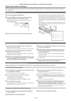
Chapter 10 Maintenance and Inspection - Inspections before shooting 4 Turn the microphone connected to the terminal to an appropriate audio source, and ensure that both level displays for CH1/CH2 change according to the audio volume. Inspecting the audio level manual adjustment 1 Press the button to display the [AUD02:INPUT] screen of SmartUI. 2 Set the [IN] item in CH1/CH2 to [FRONT]. 3 Set the [LVL] item in CH1/CH2 to [MANU]. 4 Press the button to display the [AUD01:LEVEL] screen of SmartUI. 5 Turn the microphone connected to the terminal to an appropriate audio source, and adjust the audio volume settings for CH1/CH2. 6 Select the [+] item of CH1/CH2 to ensure that the level displays increase. Inspecting the earphone and speaker 1 Adjust the dial and ensure that the speaker volume changes. 2 Connect an earphone to the terminal. Ensure that the speaker is muted and the output from the microphone is directed to the earphone. 3 Adjust the dial and ensure that the earphone volume changes. Inspections for using an external microphone 1 Connect the external microphone to the and terminals and push the / selector switch towards the side. 2 Toggle the microphone input ON/OFF switch according to the power supply for the external microphone. For microphones with an external power supply For microphones with an internal power supply 3 Press the button to display the [AUD02:INPUT] screen of SmartUI. 4 Set the [IN] item in CH1/CH2 to [REAR]. 5 Turn the microphone to an audio source, and confirm that the audio level display on the viewfinder screen or on SmartUI changes according to the audio volume. You can check each channel by connecting one microphone to each channel. Inspections for the clock, time code, and user bits 1 Set the user bits as needed. For details, refer to "User bits settings" (page 66). 2 Set the time code. For details, refer to "Setting the time code" (page 68). 3 Press the button to display the [HOME] screen of SmartUI. 4 Press the button to display [TC]. 5 Press the button to display the [SET01:TC/UB] screen of SmartUI. 6 Set the [TC_MD] item to [R‑RUN]. 7 Press the button to display the [HOME] screen of SmartUI. 8 Press the button. Ensure that the number in the counter display changes when the recording starts. 9 Press the button again. Ensure that the number in the counter display stops changing when the recording stops. 10 Press the button to display the [SET01:TC/UB] screen of SmartUI. 11 Set the [TC_MD] item to [F‑RUN]. 12 Press the button to display the [HOME] screen of SmartUI. Ensure that the number in the counter display changes regardless of the recording status. 13 Push the switch towards the side and check the date and time displayed on the viewfinder screen. If [DATE], [TIME], or the time zone is incorrect, set the correct date/ time (page 31). @@NOTE tt Note that date and time data based on [DATE], [TIME], or the time-zone setting is recorded in the clip and affects the playback order in the thumbnail operations. - 155 -
-
 1
1 -
2
-
3
-
4
-
5
-
6
-
7
-
8
-
9
-
10
-
11
-
12
-
13
-
14
-
15
-
16
-
17
-
18
-
19
-
20
-
21
-
22
-
23
-
24
-
25
-
26
-
27
-
28
-
29
-
30
-
31
-
32
-
33
-
34
-
35
-
36
-
37
-
38
-
39
-
40
-
41
-
42
-
43
-
44
-
45
-
46
-
47
-
48
-
49
-
50
-
51
-
52
-
53
-
54
-
55
-
56
-
57
-
58
-
59
-
60
-
61
-
62
-
63
-
64
-
65
-
66
-
67
-
68
-
69
-
70
-
71
-
72
-
73
-
74
-
75
-
76
-
77
-
78
-
79
-
80
-
81
-
82
-
83
-
84
-
85
-
86
-
87
-
88
-
89
-
90
-
91
-
92
-
93
-
94
-
95
-
96
-
97
-
98
-
99
-
100
-
101
-
102
-
103
-
104
-
105
-
106
-
107
-
108
-
109
-
110
-
111
-
112
-
113
-
114
-
115
-
116
-
117
-
118
-
119
-
120
-
121
-
122
-
123
-
124
-
125
-
126
-
127
-
128
-
129
-
130
-
131
-
132
-
133
-
134
-
135
-
136
-
137
-
138
-
139
-
140
-
141
-
142
-
143
-
144
-
145
-
146
-
147
-
148
-
149
-
 150
150 -
 151
151 -
 152
152 -
 153
153 -
 154
154 -
 155
155 -
 156
156 -
 157
157 -
 158
158 -
 159
159 -
 160
160 -
161
-
162
-
163
-
164
-
165
-
166
-
167
-
168
-
169
-
170
-
171
-
172
-
173
-
174
-
175
-
176
-
177
-
178
 |
 |