Panasonic CT-20SL15 20" Ctv Orion Oem - Page 8
OPTIONAL EQUIPMENT CONNECTIONS, ENGLISH, VCR Connection, Front Control Panel, Cable Box Connection - ct remote
 |
UPC - 037988055296
View all Panasonic CT-20SL15 manuals
Add to My Manuals
Save this manual to your list of manuals |
Page 8 highlights
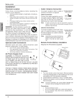
ENGLISH OPTIONAL EQUIPMENT CONNECTIONS Optional Equipment Connections Note: The remote control must be programmed with supplied codes to operate the optional equipment. VCR Connection VCRs, video disc players, video game equipment, and DSS equipment can also be connected to the video inputs. See the optional equipment manual for more information. TERMINALS ON BACK OF TELEVISION FOR CT-20SL15 Use either the S-Video or Video Connection CABLES NOT INCLUDED VCR PLAY R E FF W STOP VIDEO OUT L R ANT OUT ANT IN ICnacbolme ing Procedure FRONT A/V JACKS • Connect equipment as shown to front or rear Audio/ Video input jacks. • Select the Video mode by pressing TV/VIDEO button. • Operate optional equipment as instructed in equipment manual. Note: When the S-video cable and the video cable are connected to each jack at the same time, the S-video cable takes precedence over the video cable. Front Control Panel The front control panel can be used to access menus and switch video mode when the remote control is not available. Front panel for CT-20SL15 POWER ON/OFF Front panel for CT-27SC15/CT-27SL15 Procedure • Connect equipment to front Audio/Video input jacks. • Press TV/VIDEO button to select desired input mode. • Operate optional equipment as instructed in equipment manual. Cable Box Connection Follow this diagram when connecting your television to a Cable Box. CABLE BOX 15 ANT IN ANT OUT TERMINALS ON BACK OF TELEVISION FOR CT-20SL15 Incoming Cable CABLES NOT INCLUDED Procedure • Tune the television to channel 3 or 4 depending on the RF out setting of the cable box. • Using the cable box, tune to the premium cable channel you want to view. Digital TV - Set-Top Box (DTV-STB) or DVD Player Connection Use this diagram to connect the Panasonic DTV-STB (Digital TV-Set-Top Box) to the back of your TV. CABLES NOT SUPPLIED TERMINALS ON BACK OF DTV-STB OR DVD PLAYER DIGITAL TV OUTPUT R-AUDIO-L Y PB PR COMPONENT VIDEO INPUT TERMINALS ON BACK OF TV FOR CT-20SL15 R-AUDIO-L VIDEO S-VIDEO NTSC OUTPUT Notes: • There are three video jacks, Y, PB, and PR. Separate component color inputs provide luminance and color separation. Use the L (left) and R (right) audio inputs. • Select DTV-STB to 480i output mode. TV set can receive 480i signal only. Picture distortion will result if any other type of format is selected (i.e. 480p, 720p or 1080i). • Only one Audio input is available on rear AV jack panel. If using component Y,Pb,Pr video and L&R audio jacks, then composite video input (yellow RCA jack) can not have audio connected. 6
-
 1
1 -
2
-
 3
3 -
 4
4 -
 5
5 -
 6
6 -
 7
7 -
 8
8 -
 9
9 -
 10
10 -
 11
11 -
 12
12 -
 13
13 -
14
-
15
-
16
-
17
-
18
-
19
-
20
-
21
-
22
-
23
-
24
-
25
-
26
-
27
-
28
-
29
-
30
-
31
-
32
-
33
-
34
-
35
-
36
-
37
-
38
-
39
-
40
-
41
-
42
-
43
-
44
-
45
-
46
-
47
-
48
-
49
-
50
-
51
-
52
-
53
-
54
-
55
-
56
-
57
-
58
-
59
-
60
-
61
-
62
-
63
-
64
-
65
-
66
-
67
-
68
 |
 |
