Panasonic FV-08VQ5 Installation Instructions - Page 7
Installation, Suspension, Brackets, Mounting
 |
View all Panasonic FV-08VQ5 manuals
Add to My Manuals
Save this manual to your list of manuals |
Page 7 highlights
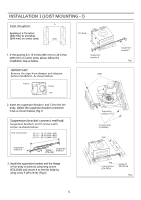
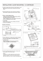
INSTALLATION II (SUSPENSION BRACKETS MOUNTING) Joist situation: A Spacing A is 16 inches (406 mm) to 24 inches (609 mm) on center joists Joists Fan body O Suspension bracket III or IV 1. If the spacing A is 16 inches (406 mm) to 24 inches (609 mm) on center joists, please follow the installation step as below. O Suspension bracket II Suspension bracket I Fig.7 2. Insert the suspension bracket I and II into the fan body and suspension bracket III or IV into the adaptor. (Select the suspension bracket connection holes as shown below) (Fig.7, Fig.8) Suspension bracket connect method: Suspension bracket I and II connect with screw I as shown below: Unit: inches (mm) 13 1/4 - 15 1/2 (336-394) 16 1/2 - 18 3/4 (419-480) 21 1/4 - 23 1/2 (540-597) Suspension bracket II Suspension • '1.4_ Screw I bracket I (ST4.2X6) 3. Install the suspension bracket to joists by using long screws (ST4.2X20) (Fig.8) and secure it to the fan body by using screw II (ST4.2X14). (Fig.9) Suspension bracket III 16 inches (406 mm) or 19 inches (483 mm) horizental joist Suspension bracket IV 24 inches (609 mm) horizental joist Joists 4 Fan body 6 Long screws (ST4.2X20) 13 1/4-15 1/2 (336-394 ) 16 1/2-18 3/4 (419-480) 21 1/4-23 1/2 ( 540-597 ) A 2 1/2-4 1/5 (64-107) 51/2-7 1/5 (140-183) B 0- (0-25.4) Unit: inches (mm) Fig.8 7
-
 1
1 -
 2
2 -
 3
3 -
 4
4 -
 5
5 -
 6
6 -
 7
7 -
 8
8 -
 9
9 -
 10
10 -
 11
11 -
 12
12
 |
 |
