Panasonic FV20VQ3 Installation Instructions - Page 5
Caution
 |
View all Panasonic FV20VQ3 manuals
Add to My Manuals
Save this manual to your list of manuals |
Page 5 highlights
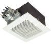
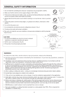
INSTALLATION I (SUSPENDED CEILING) 1. Disconnect plug connector from receptacle before starting installation. 2. Assemble suspension bracket and rubber 1 to fan body. (Fig. 1) 3. Suspend body with anchor bolts. (not supplied) (Fig. 2) 4. Remove junction box cover and secure conduit to junction box knockout hole. (7/8 inch) (Fig. 3) 5. Refer to wiring diagram Using wire nuts, connect house power wires to ventilating fan wires (Fig. 3): black to black; white to white; green to green. Replace junction box cover. 4 Screws (ST4.2X12) Suspension bracket Rubber 1 CAUTION Mount junction box cover carefully so that lead wires are not pinched. Wiring Diagram Motor Fan body Red White Black Junction box Capacitor White White Black Black Neutral Switch Power supply Live AC120V 60Hz Green Green (not included) Green Earth ground>. 4 e Earth ground Earth ground Fig. Anchor bolt Fan body Junction box Anchor bolt (Not supplied) II Rubber II and 3 Washer Anc or bolt Rubber 1 Fig. 2 Conduit 6. Install circular duct (6 inches) and secure it with tape. 7. Finish ceiling work. Ceiling hole should be aligned with fan opening. 8. Connect plug connector to receptacle. 9. Insert mounting springs into slots as shown and mount grille to fan body. (Fig. 4) Lead wires Green wires Wire nut Fig. 3 Slot Mounting spring f f Grille Fig. 4 5
-
 1
1 -
 2
2 -
 3
3 -
 4
4 -
 5
5 -
 6
6 -
 7
7 -
 8
8
 |
 |
