Panasonic FV20VQ3 Installation Instructions - Page 6
Installation, Wooden, Header
 |
View all Panasonic FV20VQ3 manuals
Add to My Manuals
Save this manual to your list of manuals |
Page 6 highlights
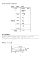
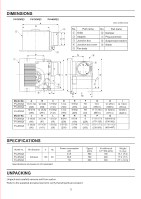
INSTALLATION II (WOODEN HEADER) 1. Install header between ceiling joists using nails or screws. (Fig. 5) 2. Install the ventilating fan to the header with long screws (ST4.2X20). (Figs. 5 & 6) inches (mm) Model No. FV-20VQ3 FV-30VQ3 FV-40VQ3 A 12 13/32 (315) 15 (380) B 17 7/8 (454) 20 13/32 (518) Ceiling joist Fan body 3. Insert the circular duct to the adapter. Remove the junction box cover and secure conduit to junction box knockout hole. (7/8 inch) (Fig. 6) 4. Refer to wiring diagram. Using wire nuts, connect house power wires to ventilating fan wires: black to black; white to white; green to green. Replace junction box cover. Ceiling joist Adapter CAUTION Mount junction box cover carefully so that lead wires are not pinched. Ceiling joist 6 Long screws (ST4.2X20) Wiring Diagram Motor Fan body Red White Black Junction box Capacitor White White Black Black Neutral SwitchPower supply Live ground_>.C120V 60Hz Green Green (not inducted) Greene Earth Earth ground Earth ground Ceiling joist Ceiling Ceiling joist Flange Header Ceiling joist Adapter Fig. 5 Circular duct Junction box cover Fig. 6 Fig. 7 5. Finish ceiling work. Ceiling hole should be aligned with the edge of the flange. (Fig. 7) 6. Mount grille to fan body. (Fig. 4 of page 5). 6
-
 1
1 -
 2
2 -
 3
3 -
 4
4 -
 5
5 -
 6
6 -
 7
7 -
 8
8
 |
 |
