| Section |
Page |
| ORDER NO. KMF0811207CE |
1 |
| 1 Safety Precautions |
3 |
| 1.1. For Service Technicians |
3 |
| 1.2. AC Caution |
3 |
| 1.3. Personal Safety Precautions |
4 |
| 1.3.1. Moving Sections of The Unit |
4 |
| 1.3.2. Live Electrical Sections |
4 |
| 1.4. Service Precautions |
5 |
| 1.4.1. Precautions to Prevent Damage From Static Electricity |
5 |
| 2 Warning |
5 |
| 2.1. About Lead Free Solder (PbF: Pb free) |
5 |
| 2.1.1. Suggested PBF Solder |
5 |
| 2.2. Discarding of P. C. Board |
6 |
| 2.3. Insulation Resistance Test |
6 |
| 2.4. Battery Caution |
6 |
| 2.4.1. Information for Users on Collection and Disposal of Old Equipment and used Batteries |
6 |
| 2.5. Laser Beam and Fuser Unit Section |
7 |
| 3 Specifications |
8 |
| 4 General/Introduction |
9 |
| 4.1. Optional Accessories |
9 |
| 4.2. Translation Lists |
9 |
| 4.2.1. Help Function |
9 |
| 4.2.2. Error Message (Report) |
10 |
| 4.2.2.1. CZECH |
10 |
| 4.2.2.2. SLOVAK |
10 |
| 4.2.2.3. HUNGARIAN |
10 |
| 4.2.3. Error Message (Display) |
11 |
| 4.2.3.1. CZECH |
11 |
| 4.2.3.2. SLOVAK |
13 |
| 4.2.3.3. HUNGARIAN |
15 |
| 4.3. Precautions for Shipping |
17 |
| 4.3.1. Necessary Items and Procedures for Each Service Type |
17 |
| 4.3.2. Repack Procedure |
20 |
| 5 Features |
30 |
| 5.1. General Features |
30 |
| 5.2. Hardware Requirements for Multi-Function Software |
30 |
| 6.1. Connection Diagram |
31 |
| 6.2. General Block Diagram |
32 |
| 6.3. Main Board Section |
35 |
| 6.3.1. Data Flow |
35 |
| 6.3.2. RTC Backup Circuit |
51 |
| 6.3.3. Modem Circuit Operation |
51 |
| 6.3.4. TEL Line Section |
52 |
| 6.3.4.1. Description of Block Diagram in Analog Section |
52 |
| 6.3.4.2. Block Diagram |
52 |
| 6.4. NCU Section |
53 |
| 6.4.1. General |
53 |
| 6.4.2. EXT. TEL. Line Relay (RY100) |
53 |
| 6.4.3. BELL Detection Circuit |
53 |
| 6.4.4. Calling Line Identification Circuit |
53 |
| 6.4.5. Remote FAX Activation Circuit |
53 |
| 6.4.6. TAM Interface Circuit |
53 |
| 6.5. ITS (Integrated Telephone System) and Monitor Section |
54 |
| 6.5.1. General |
54 |
| 6.5.1.1. Telephone Monitor |
54 |
| 6.5.1.2. Handset Circuit |
54 |
| 6.5.1.3. Monitor Circuit |
54 |
| 6.5.1.4. TAM Interface Section |
54 |
| 6.6. CIS Control Section |
55 |
| 6.7. Motor Drive Section |
56 |
| 6.7.1. Engine Motor Control Circuit |
56 |
| 6.7.1.1. BK Motor Control Circuit |
56 |
| 6.7.1.2. Color Motor Control Circuit |
57 |
| 6.7.2. Scanner Motor Drive Circuit |
59 |
| 6.7.2.1. Motor Current Control Circuit |
59 |
| 6.7.2.2. FB (FLATBED) Motor Drive Circuit |
60 |
| 6.7.2.3. ADF (AUTOMATIC DOCUMENT FEEDER) Motor Drive Circuit |
60 |
| 6.7.3. ADU (Automatic Duplex Unit (Option)) Motor Drive Circuit |
61 |
| 6.7.3.1. Motor Current Control Circuit |
61 |
| 6.7.3.2. ADU (Automatic Duplex Unit (Option)) Motor Drive Circuit |
62 |
| 6.7.4. Optional Lower Input Tray Motor (OPF Motor) Drive Circuit |
63 |
| 6.7.4.1. Motor Current Control Circuit |
63 |
| 6.7.4.2. Optional Lower Input Tray Motor (OPF Motor) Drive Circuit |
64 |
| 6.8. Timing Chart and Waveform of Scanner Motors |
65 |
| 6.8.1. Normal 1-2 Phase Excitation (Half Step) |
65 |
| 6.8.2. Flat Torque 1-2 Phase Excitation (Half Step) |
66 |
| 6.8.3. W 1-2 Phase Excitation (Quarter Step) |
67 |
| 6.8.4. Drive Mode of FB and ADF Motor |
68 |
| 6.9. Timing Chart and Waveform of Optional Unit Motors |
69 |
| 6.9.1. Normal 1-2 Phase Excitation (Half Step) |
69 |
| 6.10. Fan Section |
70 |
| 6.10.1. Fuser Fan |
70 |
| 6.10.2. PSU Fan |
71 |
| 6.11. Solenoid Driver Section |
72 |
| 6.12. LSU (Laser Scanning Unit) Section |
73 |
| 6.12.1. LSU (Laser Scanning Unit) Layout |
73 |
| 6.12.2. Circuit Diagram |
74 |
| 6.12.2.1. Block Diagram |
74 |
| 6.12.2.2. Circuit Diagram |
75 |
| 6.12.3. Timing Diagram |
76 |
| 6.13. Sensors and Switches Section |
78 |
| 6.13.1. OPC Home Sensor |
79 |
| 6.13.2. FTR Home Sensor |
80 |
| 6.13.3. Registration and Paper Pick Home Sensor |
80 |
| 6.13.4. Registration and Paper (Paper Sensor) |
81 |
| 6.13.5. Registration and Paper (Resistration Sensor) |
81 |
| 6.13.6. Registration and Paper Cassette Sensor |
82 |
| 6.13.7. Fuser Jam Sensor |
82 |
| 6.13.8. CIS Home Sensor |
83 |
| 6.13.9. ADF Document Sensor |
83 |
| 6.13.10. ADF Read Position Sensor |
84 |
| 6.13.11. Waste Toner Sensor |
84 |
| 6.13.12. Toner Sensor |
86 |
| 6.13.13. Drum Cartridge Virgin Sensor |
89 |
| 6.13.14. Waste Toner Bottle Switch |
90 |
| 6.13.15. Front/left Cover Switch |
90 |
| 6.13.16. 24V Interlock Switch |
90 |
| 6.13.17. 5V Interlock Switch |
91 |
| 6.13.18. Handset Hook Switch |
91 |
| 6.13.19. Color Registration Detection Circuit |
92 |
| 6.13.20. Humidity/Temperature Sensor Circuits |
95 |
| 6.13.20.1. Temperature Sensor (Characteristics of Temperature Detection Thermistor) |
96 |
| 6.13.20.2. Humidity Sensor (Characteristics of Humidity Detection Thermistor) |
97 |
| 6.13.21. Optional OPF Paper Sensor |
98 |
| 6.13.22. Optional OPF Jam Sensor |
98 |
| 6.13.23. Optional OPF Cassette Sensor |
99 |
| 6.13.24. Optional OPF Cover Switch |
100 |
| 6.13.25. Optional ADU Jam Sensor |
100 |
| 6.13.26. Optional ADU Cover Switch |
100 |
| 6.14. Operation Board Section |
101 |
| 6.15. LCD Section |
102 |
| 6.16. Heat Lamp Control Circuit |
103 |
| 6.17. HVU (High Voltage Power Supply Board) Section |
107 |
| 6.17.1. High Voltage Circuit |
107 |
| 6.17.2. Charge Control Circuit |
107 |
| 6.17.3. Development Bias Control Circuit |
108 |
| 6.17.4. Toner Supply Bias Control Circuit |
108 |
| 6.17.5. First Transfer Control Circuit ( FTR ) |
108 |
| 6.17.6. Second Transfer Control Circuit (STR) |
109 |
| 6.17.7. Reverse Bias Control Circuit |
109 |
| 6.17.8. Charger Error Detecting Circuit |
109 |
| 6.17.9. D/A Convertor (8bit, 12ch) Interface Circuit |
110 |
| 6.17.10. Interface |
111 |
| 6.18. Main Board Section |
112 |
| 6.18.1. Main Unit Power Supply Circuit Block Diagram |
112 |
| 6.18.2. DC-DC Power Supply Circuit (3.3V / 2.5V / 1.5V / 1.2V) |
113 |
| 6.18.3. Regulator Circuit (5V) |
115 |
| 6.18.4. Regulator Circuit (1.25V) |
115 |
| 6.18.5. Reset Circuit |
115 |
| 6.19. PSU (Low Voltage Power Supply Board) Section |
116 |
| 6.20. Mechanical Operation |
117 |
| 6.20.1. Color Motor Rotation Travel |
117 |
| 6.20.1.1. Color Motor Rotation Travel for Driving 3 Color (CMY) Drum Cartridges |
118 |
| 6.20.1.2. Color Motor Rotation Travel for Driving 3 Color (CMY) Toner Cartridges |
119 |
| 6.20.2. BK Motor Rotation Travel |
120 |
| 6.20.3. BK Motor Rotation Travel for Driving Black Drum Cartridge |
121 |
| 6.20.3.1. BK Motor Rotation Travel for Driving Accumulator Unit and Black Toner Cartridge |
122 |
| 6.20.3.2. BK Motor Rotation Travel for Driving Fuser Unit |
123 |
| 6.20.3.3. BK Motor Rotation Travel for Driving Waste Toner Cartridge |
124 |
| 6.20.3.4. BK Motor Rotation Travel for Driving Accumulator Unit |
125 |
| 6.20.4. Print Process |
126 |
| 6.20.4.1. Charging |
127 |
| 6.20.4.2. Laser Exposure and Scanning |
127 |
| 6.20.4.2.1. Laser Exposure |
127 |
| 6.20.4.2.2. Laser Scanning |
128 |
| 6.20.4.3. Developing |
128 |
| 6.20.4.4. Toner Transfer to the Accumulator Belt |
129 |
| 6.20.4.5. Paper Pickup |
129 |
| 6.20.4.6. Toner Transfer to Paper |
130 |
| 6.20.4.7. Fusing |
131 |
| 6.20.4.8. Paper Exit and Paper Switchback |
132 |
| 6.20.4.8.1. Normal Printing Mode (Not Duplex Printing Mode) |
132 |
| 6.20.4.8.2. Duplex Printing Mode (Paper Switchback) |
133 |
| 7 Location of Controls and Components |
134 |
| 7.1. Overview |
134 |
| 7.1.1. Front view |
134 |
| 7.1.2. Rear view |
134 |
| 7.2. Control Panel |
135 |
| 8 Installation Instructions |
136 |
| 8.1. Installation |
136 |
| 8.1.1. Toner Cartridge and Drum Cartridge |
136 |
| 8.1.1.1. When to replace the toner cartridge and the drum cartridge |
141 |
| 8.1.2. Recording Paper |
142 |
| 8.1.2.1. Using the paper input tray |
142 |
| 8.1.3. Handset Unit |
144 |
| 8.1.4. Documents The Unit Can Send |
147 |
| 8.1.4.1. Using the Scanner Glass |
147 |
| 8.1.4.2. Using the automatic document feeder |
147 |
| 8.1.5. Connecting to a computer |
148 |
| 8.1.6. Installing Multi-Function Station on a computer |
148 |
| 8.2. Connections |
150 |
| 9 Operating Instructions |
152 |
| 9.1. YOUR LOGO |
152 |
| 9.1.1. To Select Characters with The Dial Keypad |
153 |
| 9.1.2. To Select Characters Using [] OR [] |
153 |
| 10 Test Mode |
154 |
| 10.1. Test Functions |
154 |
| 10.1.1. DTMF Single Tone Transmit Selection |
156 |
| 10.1.2. Button Code Table |
156 |
| 11 Service Mode |
157 |
| 11.1. Programming and Lists |
157 |
| 11.1.1. Operation |
157 |
| 11.1.2. Operation Flow |
157 |
| 11.1.3. Specifications |
158 |
| 11.1.3.1. Service Mode #884: History |
158 |
| 11.1.3.2. Service Mode #852: Color Printing Test |
159 |
| 11.1.4. Service Function Table |
159 |
| 11.1.5. Memory Clear Specification |
162 |
| 11.2. User Mode (The list below is an example of the SYSTEM SETUP LIST the unit prints out.) |
163 |
| 11.3. Service Mode Settings (Example of a printed out list) |
165 |
| 11.4. History |
166 |
| 11.4.1. Description of The History Report |
167 |
| 12 Troubleshooting Guide |
168 |
| 12.1. User Recoverable Errors |
168 |
| 12.2. User Recoverable Network Errors |
171 |
| 12.3. Remote Programming |
174 |
| 12.3.1. Entering The Remote Programming Mode and Changing Service Codes |
175 |
| 12.3.2. Program Mode Table |
176 |
| 12.3.2.1. User Function |
176 |
| 12.3.2.2. Service Function |
178 |
| 12.4. Troubleshooting Details |
180 |
| 12.4.1. Outline |
180 |
| 12.4.2. Starting Troubleshooting |
180 |
| 12.4.3. Initialization |
181 |
| 12.4.4. Simple Check List |
182 |
| 12.4.5. Simplified Troubleshooting Guide |
183 |
| 12.4.5.1. Printing |
183 |
| 12.4.5.2. Jam |
184 |
| 12.4.6. Call Service Troubleshooting Guide |
186 |
| 12.4.6.1. CALL SERVICE 1 |
188 |
| 12.4.6.2. CALL SERVICE 2 |
189 |
| 12.4.6.3. CALL SERVICE 3 |
190 |
| 12.4.6.4. CALL SERVICE 4 |
191 |
| 12.4.6.5. CALL SERVICE 5 |
192 |
| 12.4.6.6. CALL SERVICE 6 |
193 |
| 12.4.6.7. CALL SERVICE 11 |
194 |
| 12.4.6.8. CALL SERVICE 12 |
195 |
| 12.4.6.9. CALL SERVICE 13 |
196 |
| 12.4.6.10. CALL SERVICE 14 |
197 |
| 12.4.6.11. CALL SERVICE 15 |
198 |
| 12.4.6.12. CALL SERVICE 16 |
199 |
| 12.4.6.13. CALL SERVICE 17 |
200 |
| 12.4.6.14. CALL SERVICE 18 |
201 |
| 12.4.6.15. CALL SERVICE 19 |
202 |
| 12.4.6.16. CALL SERVICE 20 |
203 |
| 12.4.7. Print Quality |
204 |
| 12.4.7.1. Blank Print |
204 |
| 12.4.7.2. All-black Print |
205 |
| 12.4.7.3. Missing Primary Color |
206 |
| 12.4.7.4. Light Print |
207 |
| 12.4.7.5. Repeated Spots or Lines on Print in-line with Each Other |
208 |
| 12.4.7.6. Dark Vertical Line in Print |
209 |
| 12.4.7.7. White Horizontal Line or Band in all the Color of a Print |
210 |
| 12.4.7.8. Mis-transfer, Missing Portions of Toner |
211 |
| 12.4.7.9. Dirty Background |
212 |
| 12.4.7.10. Partial Primary Color Dots |
213 |
| 12.4.7.11. Dark Irregular Streaks in Print |
213 |
| 12.4.7.12. Primary Color Irregular Streaks |
214 |
| 12.4.7.13. Ghosting |
214 |
| 12.4.7.14. Unfused or Partially Fused Printing |
215 |
| 12.4.7.15. Image is Skewed on the Paper |
216 |
| 12.4.7.16. Stains on Back of Print |
217 |
| 12.4.7.17. No Printing on Edge of Print |
218 |
| 12.4.7.18. Image is not Centered on the Print When it Should Be |
219 |
| 12.4.8. Jam |
220 |
| 12.4.8.1. Print Media Problem |
220 |
| 12.4.8.2. Print Media Skew |
221 |
| 12.4.8.3. Paper Jam at the Input Tray |
222 |
| 12.4.8.4. Paper Jams at the Registration Roller |
223 |
| 12.4.8.5. Paper Jams at the 2nd Transfer Roller |
224 |
| 12.4.8.6. Paper Jams at the Fuser Unit |
225 |
| 12.4.8.7. Paper Jam at the Exit Roller |
226 |
| 12.4.8.8. Wrong Paper Length Jams |
227 |
| 12.4.8.9. Paper Jams at the Optional Input Tray |
228 |
| 12.4.8.10. Paper Jam at Optional Automatic Duplex Unit (ADU) |
229 |
| 12.4.9. Communication Section |
230 |
| 12.4.9.1. Defective Facsimile Section |
231 |
| 12.4.9.1.1. Transmit Problem |
231 |
| 12.4.9.1.2. Sometime There is a Transmit Problem |
232 |
| 12.4.9.1.3. Receive Problem |
233 |
| 12.4.9.1.4. The Unit Can Copy, but Cannot Transmit/Receive |
234 |
| 12.4.10. Special Service Journal Reports |
235 |
| 12.4.10.1. Journal 2 |
236 |
| 12.4.10.2. Journal 3 |
237 |
| 12.4.10.3. Printout Example |
237 |
| 12.4.10.4. How to Output the Journal Report |
238 |
| 12.4.11. Initializing Error |
247 |
| 12.4.12. Analog Section |
248 |
| 12.4.12.1. Check Sheet |
248 |
| 12.4.12.2. Defective ITS (Integrated Telephone System) Section |
249 |
| 12.4.12.3. Defective TAM Interface Section |
250 |
| 12.4.13. Operation Panel Section |
251 |
| 12.4.14. Sensor Section |
252 |
| 12.4.15. Motor Section |
262 |
| 12.4.15.1. BK Motor |
262 |
| 12.4.15.2. Color Motor |
263 |
| 12.4.15.3. FB (Flatbed) Motor |
264 |
| 12.4.15.4. ADF Motor (ADF provided model only) |
265 |
| 12.4.15.5. ADU (Automatic Duplex Unit (Option)) Motor |
266 |
| 12.4.15.6. Optional Lower Input Tray (OPF Motor) |
267 |
| 12.4.16. LSU Section |
268 |
| 12.4.17. CIS Control Section |
269 |
| 12.4.18. High Voltage Value Check point |
271 |
| 12.4.19. High Voltage Section |
275 |
| 12.4.20. USB Section |
284 |
| 12.4.21. LAN Section |
288 |
| 12.4.22. Main Board Section |
293 |
| 12.4.23. PSU (Low Voltage Power Supply Board) Section |
296 |
| 12.4.23.1. Key Components for Troubleshooting |
296 |
| 12.4.23.2. Troubleshooting Flow Chart |
297 |
| 12.4.23.3. Broken Parts Repair Details |
299 |
| 12.5. Recording Paper Jam |
300 |
| 12.5.1. When the recording paper has jammed inside of the unit |
301 |
| 12.5.2. When the recording paper has jammed near the optional input tray |
305 |
| 12.5.3. When the recording paper is not fed into the unit properly |
306 |
| 12.6. Document Jams (Automatic Document Feeder) |
306 |
| 13 Service Fixture & Tools |
309 |
| 14 Disassembly and Assembly Instructions |
310 |
| 14.1. First of All |
310 |
| 14.2. Flow Chart for Disassembly |
314 |
| 14.2.1. ADF Cover Section |
314 |
| 14.2.2. FB Unit, ADF Unit and LSU Unit Section |
314 |
| 14.2.3. Rear Section |
315 |
| 14.2.4. Accumulator Unit |
315 |
| 14.2.5. Fuser Section |
316 |
| 14.3. Disassembly for Main Parts |
316 |
| 14.3.1. Remove ADF Section (1) |
316 |
| 14.3.2. Remove ADF Section (2) |
317 |
| 14.3.3. Remove ADF Section (3) |
317 |
| 14.3.4. Remove ADF Section (4) |
318 |
| 14.3.5. Remove Rear Cover |
319 |
| 14.3.6. Remove Left Cover |
319 |
| 14.3.7. Remove FB Unit and ADF Unit |
320 |
| 14.3.8. Remove FB Unit Section |
321 |
| 14.3.9. Remove FB Inner Section (1) |
322 |
| 14.3.10. Remove FB Inner Section (2) |
322 |
| 14.3.11. Remove Toner Sensor Board and Main Drive Unit |
323 |
| 14.3.12. Remove PSU Shield Cover |
324 |
| 14.3.13. Remove Front Cover |
324 |
| 14.3.14. Remove Fuser Unit |
325 |
| 14.3.15. Remove WTF Sensor Board and Registration and Paper Unit |
326 |
| 14.3.16. Open Drum Cartridge Cover |
326 |
| 14.3.17. Remove Accumulator unit |
327 |
| 14.3.18. Remove DC Motor |
327 |
| 14.3.19. Remove FTR Home Sensor Board Section |
328 |
| 14.3.20. Remove Top Cover |
328 |
| 14.3.21. Remove LSU Unit |
329 |
| 14.3.22. Remove Right Cover |
329 |
| 14.3.23. Remove Main Board |
330 |
| 14.3.24. Remove High Voltage Power Supply Board |
330 |
| 14.3.25. Remove Color Registration Sensor Board Ass'y |
331 |
| 14.3.26. Remove Fan Section |
331 |
| 14.3.27. Remove Low Voltage Power Supply Board |
332 |
| 14.4. Disassembly for Main Drive Unit |
333 |
| 14.4.1. Main Drive Unit Disassembly |
333 |
| 14.4.1.1. Main Drive Motors [No.D1] (Procedure No. D1) |
334 |
| 14.4.1.2. Fuser Idle Gear [No.D2] (Procedure No. D2) |
334 |
| 14.4.1.3. Drive Unit Bracket (S), PC Idle Gears, Accumulator Idle Gears and Joint Gear [No.D3] (Procedure No. D3) |
335 |
| 14.4.1.4. CMY Home Lever, PC Home Lever, OPC Cam Home Position Sensor Board, OPC Gear and Dev.Gear [No.D4] (Procedure No. D3 -> No. D4) |
337 |
| 14.4.1.5. Waste Toner Box Coupling and Coupling Idle Gear [No.D5] (Procedure No. D-3 -> No. D5) |
338 |
| 14.4.1.6. Accumulator Drive Cam and Accumulator Cam Idle Gear [No.D6] (Procedure No. D3 -> No. D6) |
338 |
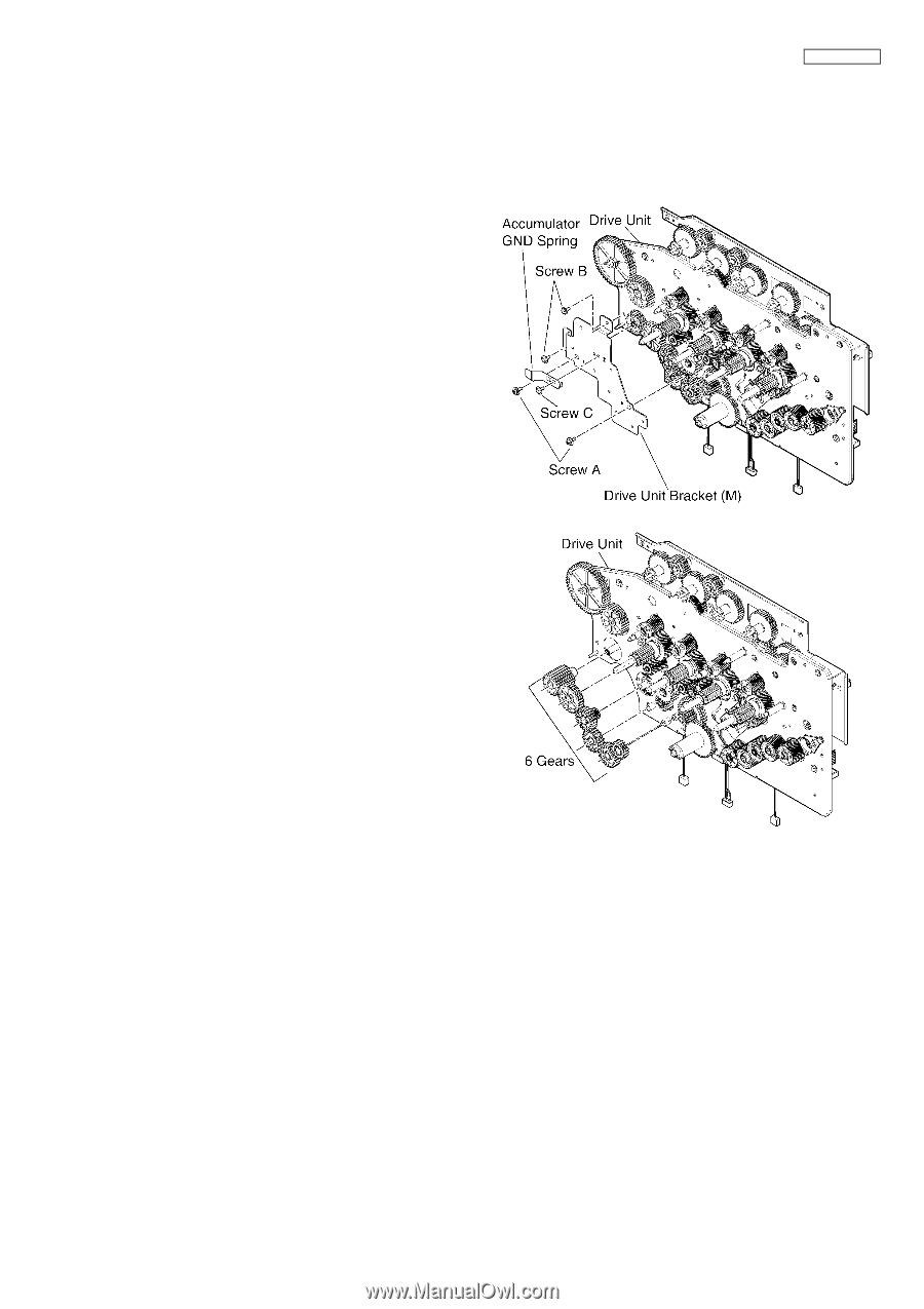
| 14.4.1.7. Drive Unit Bracket (M) and 6 Gears [No.D7] (Procedure No. D3 -> No. D7) |
339 |
| 14.4.1.8. Drive Unit Bracket (L) [No.D8] (Procedure No. D3 -> No. D7 -> D8) |
340 |
| 14.4.1.9. Accumulator Joint Pulley Gear, Feed Pulley Gear and Tension Roller [No.D9] (Procedure No. D3 -> No. D7 -> D8 -> D9) |
341 |
| 14.4.1.10. BK Changer Clutch Assembly [No.D10] (Procedure No. D3 -> No. D7 -> D8 -> D10) |
342 |
| 14.4.1.11. Accumulator Drive Clutch and Accumulator Drive Gear Solenoid [No.D11] (Procedure No. D3 -> No. D7 -> D8 -> D11) |
343 |
| 14.4.1.12. Toner Cartridge Joint Gear [No.D12] (Procedure No. D3 -> No. D7 -> D8 -> D12) |
344 |
| 14.5. How to Remove STR |
345 |
| 14.6. Note for Assembling |
347 |
| 14.6.1. Main Drive Section |
347 |
| 14.6.2. Accumulator Unit Section |
350 |
| 14.6.3. Color Registration Sensor Section |
351 |
| 14.7. Installation Position of the Lead |
352 |
| 14.7.1. Main Board Section (1) |
352 |
| 14.7.2. Main Board Section (2) |
353 |
| 14.7.3. Main Board Section (3) |
355 |
| 14.7.4. Main Cabinet Section |
356 |
| 14.7.5. Low Voltage Power Supply Board Section (1) |
357 |
| 14.7.6. Low Voltage Power Supply Board Section (2) |
358 |
| 14.7.7. Main Drive Unit Section |
359 |
| 15 Measurements and Adjustments |
361 |
| 15.1. Color Registration Skew Adjustment |
361 |
| 16 Maintenance |
364 |
| 16.1. Maintenance Items and Component Locations |
364 |
| 16.1.1. Outline |
364 |
| 16.1.2. Maintenance Check Items/Component Locations |
364 |
| 16.1.2.1. User Maintenance |
365 |
| 16.1.2.2. Service Maintenance |
365 |
| 16.1.2.2.1. Recommended Maintenance Cycle |
365 |
| 16.1.2.2.2. Lubrication |
365 |
| 16.2. Maintenance |
366 |
| 16.2.1. Cleaning the white plates and glass |
366 |
| 16.2.2. Cleaning the Document Feeder Rollers |
367 |
| 16.2.3. Cleaning the paper chute |
368 |
| 16.3. Terminal Guide of the ICs, Transistors and Diodes |
370 |
| 16.3.1. Main Board (1) |
370 |
| 16.3.2. Main Board (2) |
371 |
| 16.3.3. Toner Sensor Board |
371 |
| 16.3.4. WTF Sensor Board |
371 |
| 16.3.5. FB Relay Board |
371 |
| 16.3.6. Operation Board |
372 |
| 16.3.7. Optional ADU Board |
372 |
| 16.3.8. Optional OPF Main Board |
372 |
| 16.4. How to Replace the Flat Package IC |
373 |
| 16.4.1. Preparation |
373 |
| 16.4.2. Flat Package IC Removal Procedure |
373 |
| 16.4.3. Flat Package IC Installation Procedure |
374 |
| 16.4.4. Bridge Modification Procedure |
374 |
| 16.5. Main Board Section |
375 |
| 16.5.1. NG Example |
376 |
| 16.6. Test Chart |
377 |
| 16.6.1. ITU-T No.1 Test Chart |
377 |
| 16.6.2. ITU-T No.2 Test Chart |
378 |
| 17 Schematic Diagram |
379 |
| 17.1. For Schematic Diagram |
379 |
| 17.2. Main Board |
380 |
| 17.2.1. Main Board (1) |
380 |
| 17.2.2. Main Board (2) |
384 |
| 17.2.3. Main Board (3) |
386 |
| 17.2.4. Main Board (4) |
388 |
| 17.2.5. Main Board (5) |
390 |
| 17.2.6. Main Board (6) |
392 |
| 17.2.7. Main Board (7) |
394 |
| 17.2.8. Main Board (8) |
396 |
| 17.2.9. Main Board (9) |
398 |
| 17.2.10. Main Board (10) |
400 |
| 17.2.11. Main Board (11) |
402 |
| 17.2.12. Main Board (12) |
404 |
| 17.3. Sensor Board |
406 |
| 17.4. Scanner Board |
407 |
| 17.5. Operation Board |
408 |
| 17.6. High Voltage Power Supply Board |
410 |
| 17.6.1. High Voltage Power Supply Board (1) |
410 |
| 17.6.2. High Voltage Power Supply Board (2) |
411 |
| 17.6.3. High Voltage Power Supply Board (3) |
412 |
| 17.7. Low Voltage Power Supply Board |
413 |
| 17.8. Optional ADU Board |
414 |
| 17.9. Optional OPF Board |
415 |
| 17.10. Optional Hook Switch Board |
416 |
| 18 Printed Circuit Board |
417 |
| 18.1. Main Board |
417 |
| 18.1.1. Main Board: Component View |
417 |
| 18.1.2. Main Board: Bottom View |
418 |
| 18.2. Sensor Board |
419 |
| 18.2.1. Toner Sensor Board |
419 |
| 18.2.2. ADF Relay Board |
420 |
| 18.2.3. ADF Board |
420 |
| 18.2.4. WTF Sensor Board |
420 |
| 18.2.5. Cassette Sensor Board |
420 |
| 18.2.6. FTR Home Position Sensor Board |
420 |
| 18.2.7. Fuser Board |
421 |
| 18.2.8. Registration and Paper Sensor Board |
421 |
| 18.2.9. OPC Home Position Sensor Board |
421 |
| 18.2.10. Pick-up Home Position Sensor Board |
421 |
| 18.2.11. Sensor & Solenoid Relay Board |
421 |
| 18.2.12. CIS Home Position Sensor Board |
422 |
| 18.2.13. Color Registration Sensor Board |
422 |
| 18.2.14. Handset Relay Board |
422 |
| 18.3. Scanner Board |
423 |
| 18.3.1. FB Relay Board: Component View |
423 |
| 18.3.2. FB Relay Board: Bottom View |
423 |
| 18.3.3. CIS Relay Board |
424 |
| 18.4. Operation Board |
425 |
| 18.5. High Voltage Power Supply Board |
427 |
| 18.5.1. High Voltage Power Supply Board: Component View |
427 |
| 18.5.2. High Voltage Power Supply Board: Bottom View |
428 |
| 18.6. Low Voltage Power Supply Board |
429 |
| 18.6.1. Low Voltage Power Supply Board: Component View |
429 |
| 18.6.2. Low Voltage Power Supply Board: Bottom View |
430 |
| 18.7. Optional ADU Board |
431 |
| 18.8. Optional OPF Board |
431 |
| 18.8.1. OPF Main Board: Component View |
431 |
| 18.8.2. OPF Main Board: Bottom View |
432 |
| 18.8.3. OPF Paper Sensor Board |
432 |
| 18.8.4. OPF Sensor Board |
432 |
| 18.9. Optional Hook Switch Board |
433 |
| 19.1. Cabinet, Mechanical and Electrical Parts Location |
434 |
| 19.1.1. Operation Panel Section |
434 |
| 19.1.2. Top Cover Section |
435 |
| 19.1.3. ADF Section |
436 |
| 19.1.4. ADF Motor Section |
437 |
| 19.1.5. Bottom Cabinet Section |
438 |
| 19.1.6. Front Cabinet Section 1 |
439 |
| 19.1.7. Left Side Cabinet Section |
440 |
| 19.1.8. Rear Cabinet Section 1 |
441 |
| 19.1.9. Rear Cabinet Section 2 |
442 |
| 19.1.10. Main Drive Unit Section 1 |
443 |
| 19.1.11. Main Drive Unit Section 2 |
444 |
| 19.1.12. Main Drive Unit Section 3 |
445 |
| 19.1.13. Main Drive Unit Section 4 |
446 |
| 19.1.14. Fuser Section |
447 |
| 19.1.15. Right Side Cabinet Section |
448 |
| 19.1.16. Laser Unit Section |
449 |
| 19.1.17. Front Cabinet Section 2 |
450 |
| 19.1.18. Rear Cabinet Section 3 |
451 |
| 19.1.19. Cabinet Cover Section |
452 |
| 19.1.20. Left Side Cover Section |
453 |
| 19.1.21. Handset Section |
454 |
| 19.1.22. STR Section |
455 |
| 19.1.23. Cassette Tray Section |
456 |
| 19.1.24. KX-FAB318E/X Optional Automatic duplex Unit (ADU) Section |
457 |
| 19.1.25. KX-FAP317E/X Optional Lower Input Tray (OPF) Section 1 |
458 |
| 19.1.26. KX-FAP317E/X Optional Lower Input Tray (OPF) Section 2 |
459 |
| 19.1.27. KX-FAP317E/X Optional Lower Input Tray (OPF) Section 3 |
460 |
| 19.1.28. Actual Size of Screws and Washers |
461 |
| 19.1.29. Accessories and Packing Materials |
462 |
| 19.2. Replacement Parts List |
463 |
| 19.2.1. CABINET AND ELECTRICAL PARTS |
463 |
| 19.2.1.1. Operation Panel Section |
463 |
| 19.2.1.2. Top Cover Section |
463 |
| 19.2.1.3. ADF Section |
463 |
| 19.2.1.4. ADF Motor Section |
464 |
| 19.2.1.5. Bottom Cabinet Section |
464 |
| 19.2.1.6. Front Cabinet Section 1 |
464 |
| 19.2.1.7. Left Side Cabinet Section |
464 |
| 19.2.1.8. Rear Cabinet Section 1 |
465 |
| 19.2.1.9. Rear Cabinet Section 2 |
465 |
| 19.2.1.10. Main Drive Unit Section 1 |
465 |
| 19.2.1.11. Main Drive Unit Section 2 |
465 |
| 19.2.1.12. Main Drive Unit Section 3 |
465 |
| 19.2.1.13. Main Drive Unit Section 4 |
466 |
| 19.2.1.14. Fuser Section |
466 |
| 19.2.1.15. Right Side Cabinet Section |
466 |
| 19.2.1.16. Laser Unit Section |
466 |
| 19.2.1.17. Front Cabinet Section 2 |
467 |
| 19.2.1.18. Rear Cabinet Section 3 |
467 |
| 19.2.1.19. Cabinet Cover Section |
467 |
| 19.2.1.20. Left Side Cover Section |
467 |
| 19.2.1.21. Handset Section |
467 |
| 19.2.1.22. STR Section |
467 |
| 19.2.1.23. Cassette Tray Section |
468 |
| 19.2.1.24. KX-FAB318E/X Optional Automatic Duplex Unit (ADU) Section |
468 |
| 19.2.1.25. KX-FAP317E/X Optional Lower Input Tray (OPF) Section 1 |
468 |
| 19.2.1.26. KX-FAP317E/X Optional Lower Input Tray (OPF) Section 2 |
468 |
| 19.2.1.27. KX-FAP317E/X Optional Lower Input Tray (OPF) Section 3 |
469 |
| 19.2.1.28. Actual Size of Screws and Washers |
469 |
| 19.2.1.29. Accessories and Packing Materials |
469 |
| 19.2.2. Main Board Parts |
469 |
| 19.2.3. Sensor Board Parts |
481 |
| 19.2.3.1. Toner Sensor Board Parts |
481 |
| 19.2.3.2. ADF Relay Board Parts |
481 |
| 19.2.3.3. ADF Board Parts |
481 |
| 19.2.3.4. WTF Sensor Board Parts |
481 |
| 19.2.3.5. Cassette Sensor Board Parts |
481 |
| 19.2.3.6. FTR Home Position Sensor Board Parts |
482 |
| 19.2.3.7. Fuser Board Parts |
482 |
| 19.2.3.8. Registration and Paper Sensor Parts |
482 |
| 19.2.3.9. OPC Home Position Sensor Board Parts |
482 |
| 19.2.3.10. Pick-up Home Position Sensor Board Parts |
482 |
| 19.2.3.11. Sensor & Solenoid Relay Board Parts |
482 |
| 19.2.3.12. CIS Home Position Sensor Board Parts |
482 |
| 19.2.3.13. Color Registration Sensor Board Parts |
482 |
| 19.2.3.14. Handset Relay Board Parts |
483 |
| 19.2.4. Scanner Board Parts |
483 |
| 19.2.4.1. FB Relay Board Parts |
483 |
| 19.2.4.2. CIS Relay Board Parts |
483 |
| 19.2.5. Operation Board Parts |
483 |
| 19.2.6. High Voltage Power Supply Board Parts |
484 |
| 19.2.7. Low Voltage Power Supply Board Parts |
484 |
| 19.2.8. Optional ADU Board Parts |
484 |
| 19.2.9. Optional OPF Board Parts |
485 |
| 19.2.9.1. OPF Main Board Parts |
485 |
| 19.2.9.2. OPF Paper Sensor Board Parts |
485 |
| 19.2.9.3. OPF Sensor Board Parts |
485 |
| 19.2.9.4. Hook Switch Board Parts |
485 |
 1
1 334
334 335
335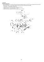 336
336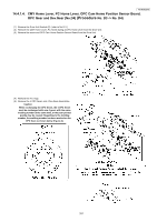 337
337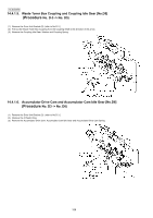 338
338 339
339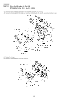 340
340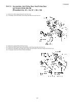 341
341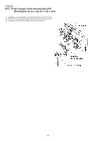 342
342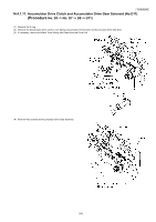 343
343 344
344