Panasonic KX-TDA600 Installation Manual - Page 197
Connection
 |
UPC - 037988851775
View all Panasonic KX-TDA600 manuals
Add to My Manuals
Save this manual to your list of manuals |
Page 197 highlights
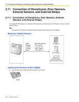
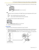
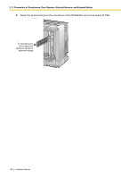
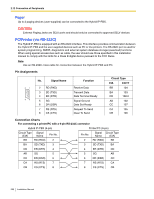
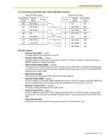
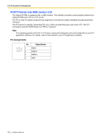
2.11 Connection of Doorphones, Door Openers, External Sensors, and External Relays 2. Pass the wires through the hole in the base cover, and attach the base cover to a wall using 2 screws. Screw To 8-pin terminal block Note Two kinds of screws are included with a KX-T30865. Please choose the appropriate kind for your wall type. : when a doorphone plate has been fixed to the wall : when you wish to install the doorphone directly onto the wall 3. Connect the wires to the screws located in the front cover. To 8-pin terminal block 4. Re-attach the 2 halves and re-insert the screw. Connection Use 8-pin and 10-pin terminal blocks (included with the card) for connection. 1. While pressing down on the hole at the top of the terminal block using a screwdriver, insert the wire into the side hole as shown below. Repeat this procedure for other doorphones, door openers, external sensors, and external relays. Refer to "2.8.2 DPH4 Card (KX-TDA0161)" and "2.8.3 EIO4 Card (KX-TDA0164)" for pin assignments. Doorphone Door Opener External Sensor/ External Relay Device Installation Manual 197
-
 1
1 -
2
-
3
-
4
-
5
-
6
-
7
-
8
-
9
-
10
-
11
-
12
-
13
-
14
-
15
-
16
-
17
-
18
-
19
-
20
-
21
-
22
-
23
-
24
-
25
-
26
-
27
-
28
-
29
-
30
-
31
-
32
-
33
-
34
-
35
-
36
-
37
-
38
-
39
-
40
-
41
-
42
-
43
-
44
-
45
-
46
-
47
-
48
-
49
-
50
-
51
-
52
-
53
-
54
-
55
-
56
-
57
-
58
-
59
-
60
-
61
-
62
-
63
-
64
-
65
-
66
-
67
-
68
-
69
-
70
-
71
-
72
-
73
-
74
-
75
-
76
-
77
-
78
-
79
-
80
-
81
-
82
-
83
-
84
-
85
-
86
-
87
-
88
-
89
-
90
-
91
-
92
-
93
-
94
-
95
-
96
-
97
-
98
-
99
-
100
-
101
-
102
-
103
-
104
-
105
-
106
-
107
-
108
-
109
-
110
-
111
-
112
-
113
-
114
-
115
-
116
-
117
-
118
-
119
-
120
-
121
-
122
-
123
-
124
-
125
-
126
-
127
-
128
-
129
-
130
-
131
-
132
-
133
-
134
-
135
-
136
-
137
-
138
-
139
-
140
-
141
-
142
-
143
-
144
-
145
-
146
-
147
-
148
-
149
-
150
-
151
-
152
-
153
-
154
-
155
-
156
-
157
-
158
-
159
-
160
-
161
-
162
-
163
-
164
-
165
-
166
-
167
-
168
-
169
-
170
-
171
-
172
-
173
-
174
-
175
-
176
-
177
-
178
-
179
-
180
-
181
-
182
-
183
-
184
-
185
-
186
-
187
-
188
-
189
-
190
-
191
-
 192
192 -
 193
193 -
 194
194 -
 195
195 -
 196
196 -
 197
197 -
 198
198 -
 199
199 -
 200
200 -
 201
201 -
 202
202 -
203
-
204
-
205
-
206
-
207
-
208
-
209
-
210
-
211
-
212
-
213
-
214
-
215
-
216
-
217
-
218
-
219
-
220
-
221
-
222
-
223
-
224
-
225
-
226
-
227
-
228
-
229
-
230
-
231
-
232
 |
 |
