Panasonic NN-SN933W NN-SN733W Owner's Manual (English) - Page 11
Operation, Oven Components Diagram
 |
View all Panasonic NN-SN933W manuals
Add to My Manuals
Save this manual to your list of manuals |
Page 11 highlights
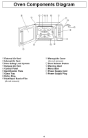
Oven Components Diagram 12 12 14 15 11 13 1 External Air Vent 2 Internal Air Vent 3 Door Safety Lock System 4 Exhaust Air Vent 5 Control Panel 6 Identification Plate 7 Glass Tray 8 Roller Ring 9 Heat/Vapor Barrier Film (do not remove) 10 Waveguide Cover (do not remove) 11 Door Release Button 12 Warning label 13 Menu label 14 Power Supply Cord 15 Power Supply Plug 9
-
 1
1 -
2
-
3
-
4
-
5
-
 6
6 -
 7
7 -
 8
8 -
 9
9 -
 10
10 -
 11
11 -
 12
12 -
 13
13 -
 14
14 -
 15
15 -
 16
16 -
17
-
18
-
19
-
20
-
21
-
22
-
23
-
24
-
25
-
26
-
27
-
28
-
29
-
30
-
31
-
32
 |
 |

9
Oven Components Diagram
1
External Air Vent
2
Internal Air Vent
3
Door Safety Lock System
4
Exhaust Air Vent
5
Control Panel
6
Identi
fi
cation Plate
7
Glass Tray
8
Roller Ring
9
Heat/Vapor Barrier Film
(do not remove)
10
Waveguide Cover
(do not remove)
11
Door Release Button
12
Warning label
13
Menu label
14
Power Supply Cord
15
Power Supply Plug
11
12
12
13
14
15