Panasonic SL-1200MK2PK Service Manual - Page 5
Measurements, Adjustments, English
 |
View all Panasonic SL-1200MK2PK manuals
Add to My Manuals
Save this manual to your list of manuals |
Page 5 highlights
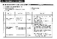
SL-1200MK2/1210MK2 • MEASUREMENTS AND ADJUSTMENTS English • Conditions of set, and instruments used 1. Remove the panel cover. 2. Remove the bottom cover (when adjusting the pitch control gain). 3. Frequency counter 4. Tester Adjustment Connection Parts adjusted Procedure 1 Pitch control ± 0% adjustment Frequency counter (+) - TP27 (-) - Earth point VR301 (Fig..3) 1. Connect the frequency counter and turn the power supply ON. 2. Set the pitch control knob to "0". (Indicator lights up.) 3. Adjust VR301 so that the frequency is 262.08 kHz ± 0.05 kHz. Pitch control gain 2 adjustment Tester (+) - CN102 terminal ® . (-) - CN102 terminal ® VR302 (Fig. 4/ 1. Set the pitch control knob to "0". 2. Pull out the connector CN102 of drive P.C.B. 3. Connect the tester to terminals,®and®of connector CN102 on the pitch control P.C.B. side. 4. Adjust VR302 so that the resistance value of the tester is 2.7 Id2± 0.1 kn. 3 Brake adjustment VR201 (Fig. 3) 1. Adjust VR201 so that the rotation at 33 r.p.m. stops within the angle of 90° -120° after depressing the stop button.
-
 1
1 -
 2
2 -
 3
3 -
 4
4 -
 5
5 -
 6
6 -
 7
7 -
 8
8 -
 9
9 -
 10
10 -
 11
11 -
12
-
13
-
14
-
15
-
16
 |
 |
