Panasonic SL-1200MK2PK Service Manual - Page 9
L-1200MK2
 |
View all Panasonic SL-1200MK2PK manuals
Add to My Manuals
Save this manual to your list of manuals |
Page 9 highlights
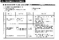
L-1200MK2 ■ ADJUSTMENTS Pitch control (fine adjustment of speed) (See Figs. 18 and 19.) When the pitch control knob is located at the center of the position after turning on the power, the green LED indicator is lit showing the operating condition for the predetermined speed (either 33-1/3 or 45 rpm). The pitch control is variable in a range of about ±8% Adjustment should be done on the basis of indicator scale. Figures on the indicator show approximate percentages for variable pitch control. When the strobe dots in 4 stages marked at the peripheral edge of the turntable appear to be stationary, variation of individual pitches is shown. (See Fig. 19.) Note: The strobe-illumination of this unit employs a strobe-illuminator LED synchronized with the precise quartz frequency. For fine adjustment of the turntable speed, be sure to effect the adjustment according to the LED illumination. The LED illumination is not synchronized with fluorescent lamps. Adjustment of arm-lift height (See Figs. 20 and 21.) The arm-lift height (distance between the stylus tip and record surface when cueing lever is raised) has been adjusted at the factory before shipping to approximately 8.13mm. If the clearance becomes too narrow or too wide, turn the adjustment screw clockwise or counterclockwise, while pushing the arm lift down. Clockwise rotation -distance between the record and stylus tip is decreased, Counterclockwise rotation -distance between the record and stylus tip is increased, Note: As the adjusting screw has hexagonal head, be sure to make the adjustment while depressing the arm lift, or the screw will not move freely. Also be sure that the hexagonal head retracts correctly into the arm lift when the latter is released. Adjustment of the tonearm height (See Fig. 22.) The height of the tonearm can be adjusted up to 6 mm, and a scale is provided on the adjust ring in 0.5 mm increments. Be sure to set the proper arm height using the adjust ring scale and referring to the table. Height of cartridge (mm) Scale reading on the arm-height __ _ (H) adjust ring 15 0 16 1 17 2 18 3 19 4 20' 5 21 6 For example, if the cartridge height is 17.5 mm, the armheight adjust ring should be pOsitioned at the intermediate location between 2 and 3 on the scale. (See Fig. 22.) Caution: Be sure to lock the tonearm by turning the arm lock knob in the direction indicated by the arrow after finishing the height adjustment for the tonearm, Lubrication (See Fig. 23.) Apply 2 or 3 drops of oil once after every 2000 hours' of operation. The time interval is much longer than that for conventional type motors (200-500 hours). Please pup-chase original oil. (Part number is SFWO 010.) 8 m (6/18-33/64") Fig. 20 Ant screw lift bar Fig. 21 0 S0 . 0 • • es. tp.pd.en ntat"wi£ty at the D., 1,O5. O! appea:s strAtkmaly at Dep.i.ch of 33. giOplo% 9.111t.onvy el me CO C.% 918.!•?..,Vy II P.e wttn of 31% Fig. 18 Fig. 19 Fig. 22 Fig. 23
-
 1
1 -
2
-
3
-
 4
4 -
 5
5 -
 6
6 -
 7
7 -
 8
8 -
 9
9 -
 10
10 -
 11
11 -
 12
12 -
 13
13 -
 14
14 -
15
-
16
 |
 |
