Panasonic WJHD220 WJHD220 User Guide - Page 17
Alarm Connection, External Recording Connection, Time Adjusting Connection, Notes
 |
View all Panasonic WJHD220 manuals
Add to My Manuals
Save this manual to your list of manuals |
Page 17 highlights
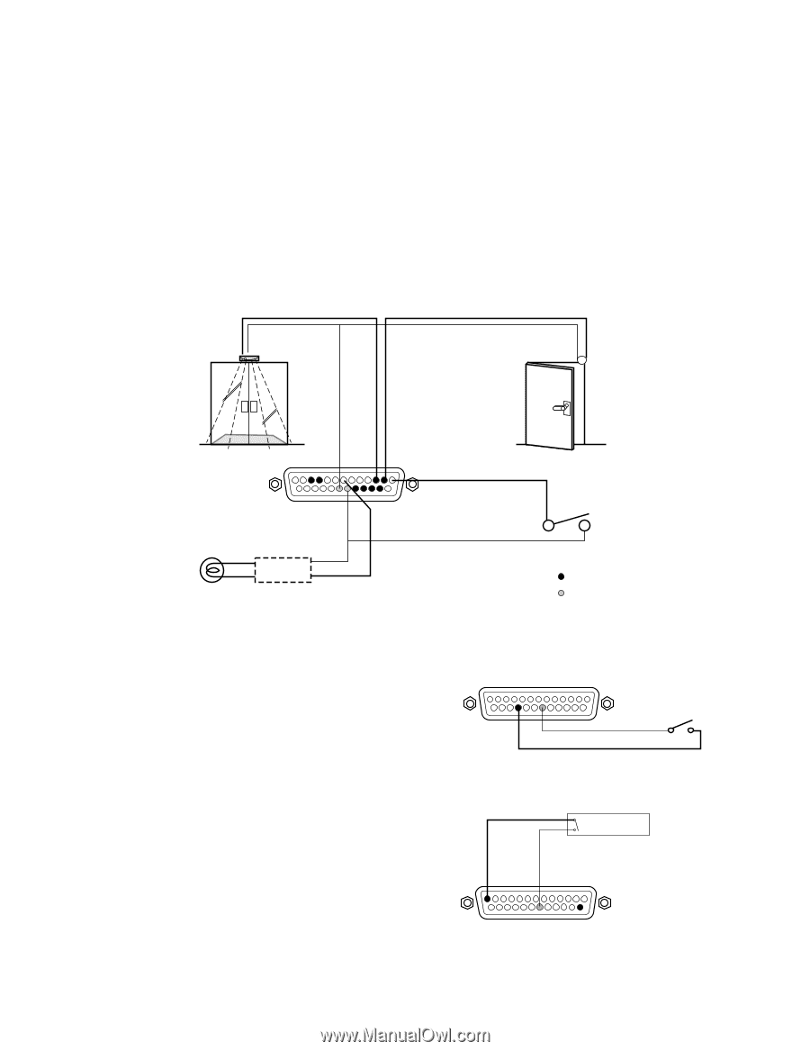
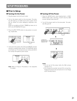
Notes: • Input rating: Low-active, non-voltage normally open (N.O.) contact • Output rating for pin #4 Alarm Recovery Out *1: High-active with a 200 Ω resistor pulled up to +5 V • Output rating for pin #7 Alarm Out 2 *2: High-active with a 4.7 kΩ resistor pulled up to +12 V • Output rating for pin #6 Alarm Out 1: Low-active, maximum load capacity of +12 V 100 mA • Output rating for other pins: Low-active, maximum load capacity of 24 V 100 mA , open-collector with a 4.7 kΩ resistor pulled up to +5 V inside • Pin #24 Sequence In receives a close contact input to advance the sequence one step. This input does not start a sequence but forwards the presently running sequence by one step. • Pin #25 Sequence Out supplies a negative pulse when the sequence running on the multiscreen monitor advances one step. G Alarm Connection There are eight alarm inputs, while two outputs are provided with different driving capacity. Sensor Door Switch #3 Alarm In 2 #2 Alarm In 1 Alarm Indicator External Alarm Reset Switch Relay *1 Alarm Input Terminals #7 Alarm Out 2 *2 Signal Ground Terminals *1: Use when the indicator exceeds over the drive capacity of the alarm out terminal. *2: Connect to #6 Alarm Out 1 when using a low-active device. G External Recording Connection The recording mode will change from the internal timer mode to the external mode (EXT REC MODE) specified in REC SETUP menu when the switch is turned on. G Time Adjusting Connection The internal timer is calibrated with this input. #22 External Recording Mode Master Clock Non-voltage N.O. contact N.O.=Normally Open #13 Time Adjust In 17
-
 1
1 -
2
-
3
-
4
-
5
-
6
-
7
-
8
-
9
-
10
-
11
-
 12
12 -
 13
13 -
 14
14 -
 15
15 -
 16
16 -
 17
17 -
 18
18 -
 19
19 -
 20
20 -
 21
21 -
 22
22 -
23
-
24
-
25
-
26
-
27
-
28
-
29
-
30
-
31
-
32
-
33
-
34
-
35
-
36
-
37
-
38
-
39
-
40
-
41
-
42
-
43
-
44
-
45
-
46
-
47
-
48
-
49
-
50
-
51
-
52
-
53
-
54
-
55
-
56
-
57
-
58
-
59
-
60
-
61
-
62
-
63
-
64
-
65
-
66
-
67
-
68
-
69
-
70
-
71
-
72
-
73
-
74
-
75
-
76
-
77
-
78
-
79
-
80
-
81
-
82
-
83
-
84
-
85
-
86
-
87
-
88
-
89
-
90
-
91
-
92
-
93
-
94
-
95
-
96
-
97
-
98
-
99
-
100
-
101
-
102
-
103
 |
 |