Panasonic fv05vf2 FV05VFA2 User Guide - Page 6
Installation, Joist, Mounting
 |
View all Panasonic fv05vf2 manuals
Add to My Manuals
Save this manual to your list of manuals |
Page 6 highlights
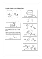
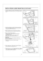
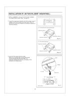
INSTALLATION 11 (JOIST MOUNTING-II) 1. Remove adaptor from fan body before starting installation. 2. Insert the suspension bracket into the adaptor and secure it to joists by using long screws (ST4.2X20) (Fig. 7) Keep the distance B (7/8 inch, 21.6mm) for the thickness of ceiling board. If spacing A between joists is 21 1/4 to 23 1/2 inches, connect suspension bracket II and III (C4 mark to C4 mark) according to page 4 Select the suspension bracket according to spacing A as shown below. Spacing A between Joists inches (mm) 13 1/4-15 1/2 ( 336-394 ) suspension bracket suspension bracket I 161/2-18 3/4 ( 419-480 ) suspension bracket III 21 1/4-231/2 ( 540-597 ) suspension bracket II&III 3. Follow step 5 to 7 of the Installation I (page 5) to complete the duct work and wiring. 4. Insert the suspension bracket into fan body (refering to step 2 of Installation I, page 4) Adaptor 2 Long screws (ST4.2X20) Joists 2 Long screws (ST4.2X20) A 13 1/4-15 1/2 336-394) 16 1/2-183/4 419-480) 21 1/4-23 1/2 540-597) inches (mm) 7 8 (21.6) 5. Insert the fan body into joists. (Fig. 8) IMPORTANT: Make sure that adaptor claws are properly inserted into fan body slots. Joist Duct Conduit Adaptor Fig. 7 Junction box cover Adaptor claws 6 Fan body Slots Duct tape Fig. 8
-
 1
1 -
 2
2 -
 3
3 -
 4
4 -
 5
5 -
 6
6 -
 7
7 -
 8
8 -
 9
9 -
 10
10 -
 11
11
 |
 |
