Panasonic fv05vf2 FV05VFA2 User Guide - Page 7
ST4.2X20
 |
View all Panasonic fv05vf2 manuals
Add to My Manuals
Save this manual to your list of manuals |
Page 7 highlights
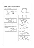
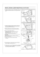
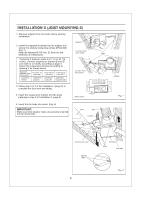
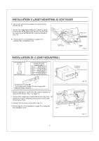
INSTALLATION II (JOIST MOUNTING-II) CONTINUED 6. Secure the fan body to adaptor by using thumb screw (Fig. 9) 7. Secure the suspension bracket to joists by using long screws (ST4.2X20) and secure it to fan body by using screw II(ST4.2X10) in vertical direction (Fig. 9) 8. Follow step 8-9 of Installation I (page 5) to complete the installation work. 2 Long screws (ST4.2X20) Screw II (ST4.2X10) Receptacle 0 Thumb screw Fig. 9 INSTALLATION DI ( I-JOIST MOUNTING ) 4 kinds of I-joist inches (mm) C1 9/16 (14.3) C2 11/16 (17.5) C C3 31/32 (24.6) C4 1 17/32 (38.9) C3 O C4 ci C2 Suspension bracket ID The suspension bracket III can comply with different kinds of I -joist. 1. Before installation, secure the fan body to adaptor by using thumb screw. (Fig. 1 of page 4) 2. Connect the suspension bracket DI to fan body. (Fig. 10) (select the hole by checking I -joist size fix the screw to the frame hole.) 3. Connect the fan body to the I -joist. (Fig. 11) 4. Follow step 5 to 9 of installation I (page 5) to complete the installation work. O )) I joist Suspension bracketIII Screw II(ST4.2X10) Fig. 10 ) 4 Long screws (ST4.2X20) Fig. 11 7
-
 1
1 -
 2
2 -
 3
3 -
 4
4 -
 5
5 -
 6
6 -
 7
7 -
 8
8 -
 9
9 -
 10
10 -
 11
11
 |
 |
