Philips 26PF9966 Quick start guide - Page 3
Ooking, P The, Elevision, Av1 - hdmi setting
 |
UPC - 037849948309
View all Philips 26PF9966 manuals
Add to My Manuals
Save this manual to your list of manuals |
Page 3 highlights
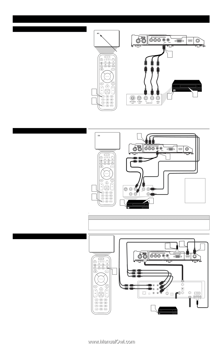
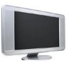
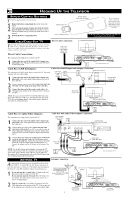
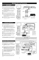
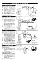
HOOKING UP THE TELEVISION AV1 INPUTS The audio/video input jacks on the bottom panel of the TV are for direct picture and sound connections between the TV and a VCR (or similar device) that has audio/video output jacks. 1 Connect the AV1 In(put) cable to one end of an RCA type VIDEO (yellow) cable to the supplied Audio/Video adapter. Connect the other end of the Adapter to the AV1 in jack on the bottom of the TV. 2 Connect the AV1 In(put) cable to one end of the RCA type AUDIO (red and white) cables to the supplied Audio/Video adapter. 3 Turn the VCR or accessory device and the TV On. 4 Press the AV+ button and the number 1 button on the remote control to select the AV1 channel for the accessory device. AV1 will appear in the upper left corner on the TV screen when tuned properly. You can also press and hold the AV+ button to toggle through the various channels until AV1 appears on the screen. 3 5 With the VCR (or accessory device) ON and a prerecorded tape (CD, DVD, etc.) inserted, press the PLAY button to 3 view the tape on the television. BOTTOM OF TV TUNE TO AV1 CHANNEL AUDIO IN (RED/WHITE) 1 VIDEO IN (YELLOW) BACK OF VCR (or Accessory device) 2 4 VCR (or accessory device) (EQUIPPED WITH VIDEO AND AUDIO OUTPUT JACKS) COMPONENT (CVI) INPUTS Component Video inputs provide the highest possible color and picture resolution in the playback of digital signal source material, such as with DVD players. 1 Connect the Component (Y, Pb, Pr) Video OUT jacks from the DVD player (or similar device) to the COMP(onent) VIDEO Input (Y green, Pb blue, Pr red) jacks on the bottom of the TV. When using the Component Video Inputs, it is best not to connect a signal to the AV1 in Video Jack. 2 Connect the red and white AUDIO CABLES to the Audio (left and right) output jacks on the rear of the accessory device to the Audio Adapter supplied (L and R). Connect the adapter into the AV1 In Input Jacks on the TV. 3 Turn the TV and the DVD (or digital accessory device) ON. 4 Press the AV+ button and the Number 1 button on the remote control to select the CVI channel. CVI will appear in the upper left corner of the TV screen. 5 Insert a DVD disc into the DVD player and press the PLAY ᮣ button on the DVD Player. NOTE: When using additional accessories, only one external source will be audible, as there is only one AV1 Input jack. 1 BOTTOM OF TV AUDIO CABLES (RED/WHITE) 2 COMPONENT VIDEO CABLES (Green, Blue, Red) 4 4 S-VIDEO VIDEO AUDIO OUT OUT OUT L 3 COMP VIDEO Y Pr Pb 5 ACCESSORY DEVICE EQUIPPED WITH COMPONENT VIDEO OUTPUTS. The CVI connection will be dominate over the AV1 in Video Input. When a Component Video Device is connected as described, it is best not to have a video signal connected to the AV1 in Video Input jack. HELPFUL HINT The description for the component video connectors may differ depending on the DVD player or accessory digital source equipment used (for example, Y, Pb, Pr; Y, B-Y, R-Y; Y, Cr, Cb). Refer to your DVD or digital accessory owner's manual for definitions and connection details. HD (HIGH DEFINITION) INPUTS HD1 If your using a High Definition receiver that can transmit high definition programming, the TV can except those signals through the HD Inputs located on the bottom of the TV. 1 For Digital Connection, connect the HDMI connector of the HD Receiver (or similar device) to the HDMI Input jacks on the bottom of the TV. OR 2 For Analog Connection, use Component Video cables to connect the Component (Y, Pb, Pr) Video Out jacks of the HD Receiver (or similar device) to the VGA adapter (supplied with the TV). Connect the other end of the adapter to the VGA Input jacks on the bottom of the TV. 3 Connect the red and white audio adapter to RCA type Audio Cables. Connect the audio adapter to the PC/HD Audio Input jack on the bottom of the TV. 4 Turn the TV and the HD Receiver ON. 5 Press the HD Mode button to set the TV into the HD Mode and tune to the HD signal. Note: The Audio/Video cables needed for this connection are not supplied with your TV. Please contact your dealer or Philips at 800-531-0039 for information about purchasing the needed cables. BOTTOM OF TV Analog Connection 2 1 3 COMPONENT 5 VIDEO CABLES (Green, Blue, Red) Digital Connection AUDIO CABLES AUDIO L Y R PB RF PR PHONE JACK REMOTE VIDEO in 1 Rear of HD Receiver (Illustration is for reference only. Your HD Receiver's jack panel may be labeled differently. 4 AUDIO VCR CONTROL DIGITAL AUDIO OUT OUT TO TV CH 3 CH 4 HDMI VIDEO in 2 S-VIDEO IN FROM ANT SATELLITE IN Coxial Cable Lead-in fom Cable Outlet, Cable Converter Box, or VHF/UHF Antenna Coaxial cable Lead-in from Satellite Dish or Antenna HD RECEIVER EQUIPPED WITH COMPONENT VIDEO OUTPUTS. 3
-
 1
1 -
 2
2 -
 3
3 -
 4
4
 |
 |