Pioneer 507CMX Operating Instructions - Page 16
Connection panel PDP-607CMX - pdp speakers
 |
UPC - 012562824390
View all Pioneer 507CMX manuals
Add to My Manuals
Save this manual to your list of manuals |
Page 16 highlights
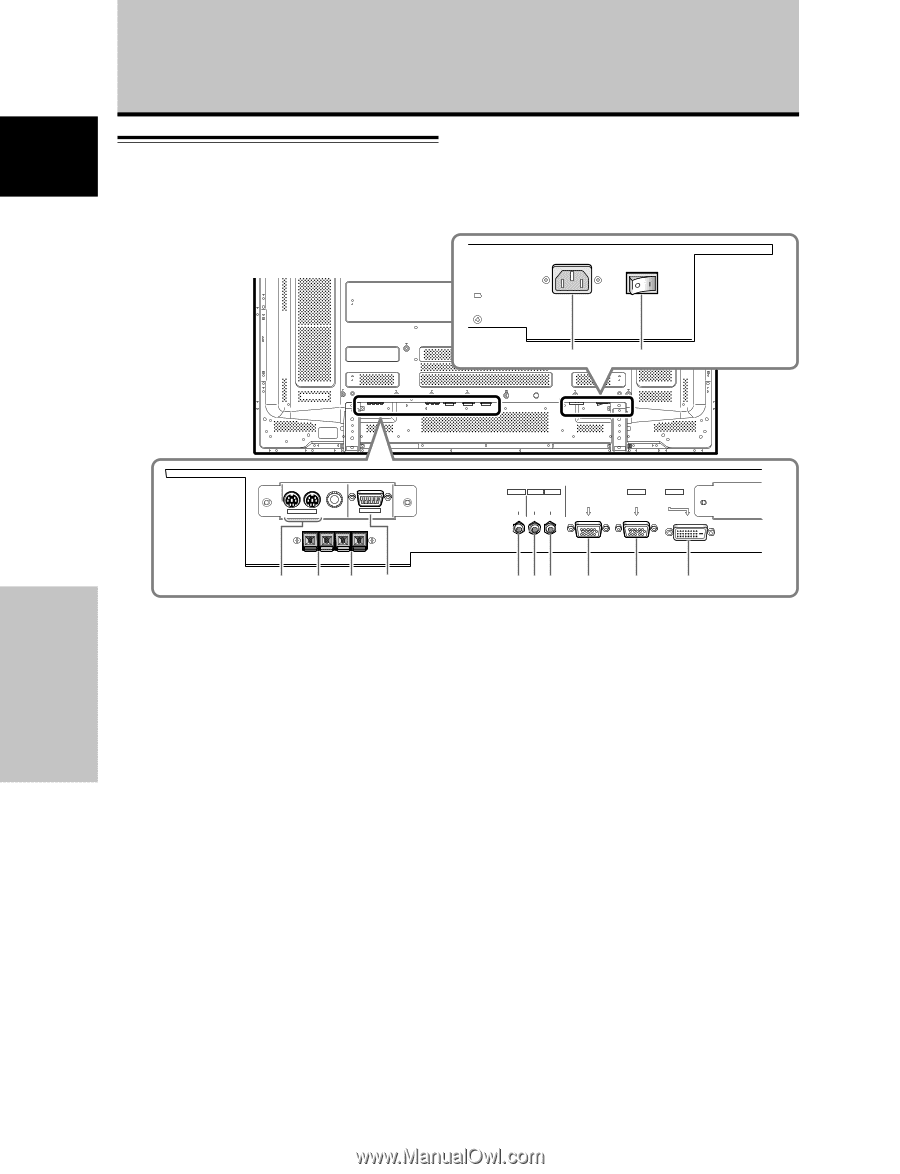
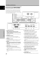
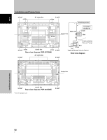
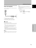
English Part Names and Functions Connection panel (PDP-607CMX) The connection panel is provided with two video input terminals and one video output terminal. Audio input/ output and speaker output terminals are also provided. For instructions regarding connections, consult the pages noted in parentheses by each item. - = Part Names and Functions IN OUT COMBINATION RS-232C OUTPUT INPUT1 INPUT2 AUDIO AUDIO AUDIO ANALOG RGB OUT (D-Sub) INPUT1 ANALOG RGB IN (D-Sub) INPUT2 DIGITAL RGB (DVI-D) 1 23 4 1 COMBINATION IN/OUT Never connect any component to these connectors without first consulting your Pioneer installation technician. These connectors are used for Plasma Display setup adjustments. 2 SPEAKER (R) terminal For connection of an external right speaker. Connect a speaker that has an impedance of 6 Ω (page 14). 3 SPEAKER (L) terminal For connection of an external left speaker. Connect a speaker that has an impedance of 6 Ω (page 14). 4 RS-232C Never connect any component to this connector without first consulting your Pioneer installation technician. This connector is used for Plasma Display setup adjustments. 5 AUDIO (OUTPUT) (Stereo mini jack) Use to output the audio of the selected source component connected to this unit to an AV amplifier or similar component. Note: No sound is produced from the AUDIO (OUTPUT) jack when the MAIN POWER switch is set to OFF or ON (standby) (page 14). 10 En 567 8 9 0 6 AUDIO (INPUT1) (Stereo mini jack) Use to obtain sound when INPUT1 is selected. Connect the audio output jack of components connected to INPUT1 to this unit (page 14). 7 AUDIO (INPUT2) (Stereo mini jack) Use to obtain sound when INPUT2 is selected. Connect the audio output jack of components connected to INPUT2 to this unit (page 14). 8 ANALOG RGB OUT (INPUT1) (mini D-sub 15 pin) Use the ANALOG RGB OUT (INPUT1) terminal to output the video signal to an external monitor or other component. Note: The video signal will not be output from the ANALOG RGB OUT (INPUT1) terminal when the main power of this unit is off or in standby mode.(page 13) 9 ANALOG RGB IN (INPUT1) (mini D-sub 15 pin) For connection of a personal computer (PC) or similar component. Make sure that the connection made corresponds to the format of the signal output from the connected component (page 13). 0 DIGITAL RGB (INPUT2) (DVI-D jack) Use to connect a computer. Note: This unit does not support the display of copyguard-protected video signals (page 13). - AC IN Use to connect the supplied power cord to an AC outlet (page 15). = MAIN POWER switch Use to switch the main power of the unit on and off.
-
 1
1 -
2
-
3
-
4
-
5
-
6
-
7
-
8
-
9
-
10
-
 11
11 -
 12
12 -
 13
13 -
 14
14 -
 15
15 -
 16
16 -
 17
17 -
 18
18 -
 19
19 -
 20
20 -
 21
21 -
22
-
23
-
24
-
25
-
26
-
27
-
28
-
29
-
30
-
31
-
32
-
33
-
34
-
35
-
36
-
37
-
38
-
39
-
40
-
41
-
42
-
43
-
44
-
45
-
46
-
47
-
48
-
49
-
50
-
51
-
52
-
53
-
54
-
55
-
56
-
57
-
58
-
59
-
60
-
61
-
62
-
63
-
64
-
65
-
66
-
67
-
68
-
69
-
70
-
71
-
72
-
73
-
74
-
75
-
76
-
77
-
78
-
79
-
80
-
81
-
82
-
83
-
84
-
85
-
86
-
87
-
88
-
89
-
90
-
91
-
92
-
93
-
94
-
95
-
96
-
97
-
98
-
99
-
100
-
101
-
102
-
103
-
104
-
105
-
106
-
107
-
108
-
109
-
110
-
111
-
112
-
113
-
114
-
115
-
116
-
117
-
118
-
119
-
120
-
121
-
122
-
123
-
124
-
125
-
126
-
127
-
128
-
129
-
130
-
131
-
132
-
133
-
134
-
135
-
136
-
137
-
138
-
139
-
140
-
141
-
142
-
143
-
144
-
145
-
146
-
147
-
148
-
149
-
150
-
151
-
152
 |
 |