Pioneer DEH P410UB Installation Manual
Pioneer DEH P410UB - Premier Radio / CD Manual
 |
UPC - 012562941363
View all Pioneer DEH P410UB manuals
Add to My Manuals
Save this manual to your list of manuals |
Pioneer DEH P410UB manual content summary:
- Pioneer DEH P410UB | Installation Manual - Page 1
CD RECEIVER AUTORADIO CD RADIO CD DEH-P410UB Installation Manual Manuel d'installation Manual de instalación Printed in China Imprimé en Chine UC Installation Note • Check all connections and systems before final installation. • Do not use unauthorized parts. The - Pioneer DEH P410UB | Installation Manual - Page 2
des pièces disponibles dans le commerce lors de l'installation. Écrou Pare-feu ou support métallique Attache en métal Vis Vis (M4˜8) • Assurez-vous que l'appareil est bien fixé. Une installation instable peut entraîner un fonctionnement incorrect de l'unité (des interruptions au niveau du son, par - Pioneer DEH P410UB | Installation Manual - Page 3
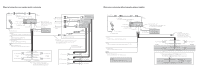
9 in.) 4. iPod 1. USB cable Connect to separately sold USB device. 3. Rear Wired remote input Hard-wired remote control adaptor can be connected (sold separately). 11. IP-BUS input (Blue) 13. Multi-CD Change the initial setting of this unit. The subwoofer output of this unit is monaural. 43 - Pioneer DEH P410UB | Installation Manual - Page 4
sold USB device. 2. This product 3. Rear output 4. iPod 5. Dock connector 6. Interface cable 7. Front output 8. Antenna jack 9. Subwoofer output 10. Wired remote input Hard-wired remote control adaptor can be connected (sold separately). 11. IP-BUS input (Blue) 12. IP-BUS cable 13. Multi-CD player - Pioneer DEH P410UB | Installation Manual - Page 5
Nota • Cuando se instale esta unidad en un Fig. 2) 1. Cable USB Conecte al dispositivo USB vendido separamente. 2. Este producto 3. Salida trasera 4. iPod 5. Conector de acoplamiento BUS (Azul) 12. Cable IP-BUS 13. Reproductor de Multi-CD (vendido separadamente) 14. Fusible (10 A) 15. Amarillo Conecte
-
 1
1 -
 2
2 -
 3
3 -
 4
4 -
 5
5
 |
 |
Installation
English
Installation
English
Note
•
Check all connections and systems before final
installation.
•
Do not use unauthorized parts. The use of
unauthorized parts may cause malfunctions.
•
Consult with your dealer if installation requires
drilling of holes or other modifications of the
vehicle.
•
Do not install this unit where:
—
it may interfere with operation of the vehicle.
—
it may cause injury to a passenger as a result
of a sudden stop.
•
The semiconductor laser will be damaged if it
overheats. Install this unit away from hot places
such as near the heater outlet.
•
Optimum performance is obtained when the unit
is installed at an angle of less than 60°.
60
°
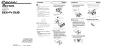
DIN Front/Rear-mount
This unit can be properly installed either from
“Front” (conventional DIN Front-mount) or
“Rear” (DIN Rear-mount installation, utilizing
threaded screw holes at the sides of unit
chassis). For details, refer to the following
installation methods.
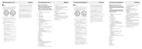
DIN Front-mount
Installation with metal strap and
screws
1. Insert the mounting sleeve into the
dashboard.
• When installing in a shallow space, use a
supplied mounting sleeve. If there is enough
space behind the unit, use factory supplied
mounting sleeve.
2. Secure the mounting sleeve by
using a screwdriver to bend the
metal tabs (90°) into place.
Dashboard
Mounting sleeve
53
182
3. Install the unit.
• Use commercially available parts when
installing.
Screw (M4
8)
Screw
Metal strap
Nut
Filrewall or
metal support
• Make sure that the unit is installed securely
in place. Unstable installation may cause this
unit to malfunction, such as sound skip.
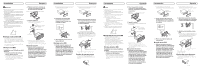
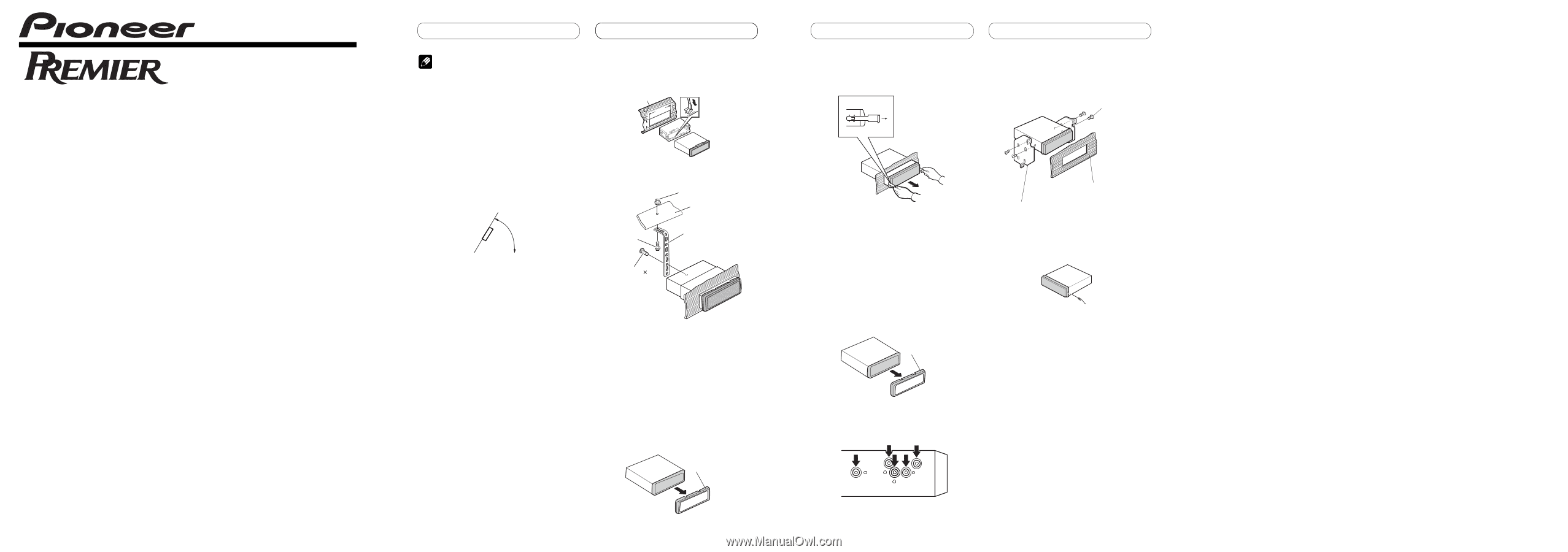
Removing the Unit
1. Extend top and bottom of the trim
ring outwards to remove the trim
ring.
When reattaching the trim
ring, push the trim ring onto the
unit until it clicks. (If the trim ring is
attached upside down, the trim ring
will not fit properly.)
• It becomes easy to remove the trim ring if the
front panel is released.
Trim ring
2. Insert the supplied extraction keys
into both sides of the unit until
they click into place.
3. Pull the unit out of the dashboard.
DIN Rear-mount
1.
Extend top and bottom of the trim
ring outwards to remove the trim
ring. When reattaching the trim ring,
push the trim ring onto the unit until
it clicks. (If the trim ring is attached
upside down, the trim ring will not
fit properly.)
• It becomes easy to remove the trim ring if the
front panel is released.
Trim ring
2. Determine the appropriate position
where the holes on the bracket and
the side of the unit match.
3. Tighten two screws on each side.
• Use either truss screws (5 mm × 8 mm)
or flush surface screws (5 mm × 9 mm),
depending on the shape of screw holes in the
bracket.
Dashboard or Console
Factory radio mounting bracket
Screw
Fastening the front panel
If you do not plan to detach the front panel,
the front panel can be fastened with supplied
screw.
Screw
<KNANX>
<08H00000>
Printed in China
Imprimé en Chine
<YRD5263-A/S> UC
Installation Manual
Manuel d’installation
Manual de instalación
CD RECEIVER
AUTORADIO CD
RADIO CD
DEH-P410UB