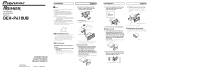
Pioneer DEH P410UB Installation Manual - Page 3
When using a subwoofer without using the optional amplifier, When not connecting a rear speaker lead - usb
 |
UPC - 012562941363
View all Pioneer DEH P410UB manuals
Add to My Manuals
Save this manual to your list of manuals |
Page 3 highlights
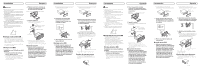
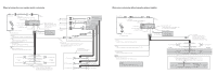
When not connecting a rear speaker lead to a subwoofer 50 cm (20 in.) 4. iPod 1.5 m (4 ft. 9 in.) 1. USB cable Connect to separately sold USB device. 3. Rear output 2. This product 20 cm (7-7/8 in.) 7. Front output 8. Antenna jack 9. Subwoofer output 14. Fuse (10 A) 5. Dock connector 6. Interface cable 15. Yellow Connect to the constant 12 V supply terminal. 16. Red Connect to terminal controlled by ignition switch (12 V DC). 17. Orange/white Connect to lighting switch terminal. 10. Wired remote input Hard-wired remote control adaptor can be connected (sold separately). 11. IP-BUS input (Blue) 13. Multi-CD player 12. IP-BUS cable (sold separately) 18. Black (chassis ground) Connect to a clean, paint-free metal location. 32. To rear output 33. To front output 34. To subwoofer output 36. Power amp (sold separately) 35. Connect with RCA cables (sold separately) 36. Power amp (sold separately) 36. Power amp (sold separately) 38. System remote control 37. Blue/white Connect to system control terminal of the power amp or auto-antenna relay control terminal (max. 300 mA 12 V DC). 39. Perform these connections when using the optional amplifier. 23. Front speaker 24. Left 30. Rear speaker 19. White 20. White/black 26. Green 27. Green/black 21. Gray 22. Gray/black 28. Violet 29. Violet/black 23. Front speaker 25. Right 30. Rear speaker 31. With a 2 speaker system, do not connect anything to the speaker leads that are not connected to speakers. 40. Subwoofer 23. Front speaker 30. Rear speaker 40. Subwoofer 23. Front speaker 30. Rear speaker When using a subwoofer without using the optional amplifier 50 cm (20 in.) 1.5 m (4 ft. 9 in.) 4. iPod 1. USB cable Connect to separately sold USB device. 3. Rear output 2. This product 7. Front output 8. Antenna jack 9. Subwoofer output 14. Fuse (10 A) 5. Dock connector 6. Interface cable 15. Yellow Connect to the constant 12 V supply terminal. 16. Red Connect to terminal controlled by ignition switch (12 V DC). 17. Orange/white Connect to lighting switch terminal. 20 cm (7-7/8 in.) 10. Wired remote input Hard-wired remote control adaptor can be connected (sold separately). 11. IP-BUS input (Blue) 13. Multi-CD player 12. IP-BUS cable (sold separately) 23. Front speaker 24. Left 42. Subwoofer (4 Ω) 19. White 20. White/black 26. Green 24. Green/black 37. Blue/white Connect to system control terminal of the power amp or auto-antenna relay control terminal (max. 300 mA 12 V DC). 21. Gray 22. Gray/black 28. Violet 29. Violet/black 23. Front speaker 25. Right 42. Subwoofer (4 Ω) 18. Black (chassis ground) Connect to a clean, paint-free metal location. 41. Note: Change the initial setting of this unit. The subwoofer output of this unit is monaural. 43. When using a subwoofer of 70 W (2 Ω), be sure to connect with Violet and Violet/black leads of this unit. Do not connect anything with Green and Green/black leads. 26. Green 44. Not used. 27. Green/black 28. Violet 29. Violet/black 45. Subwoofer (4 Ω) 2
-
 1
1 -
 2
2 -
 3
3 -
 4
4 -
 5
5
 |
 |
