Pioneer DEH-P510UB Installation Manual - Page 6
Installation, English, Conexión de las unidades, Español
 |
UPC - 012562945156
View all Pioneer DEH-P510UB manuals
Add to My Manuals
Save this manual to your list of manuals |
Page 6 highlights
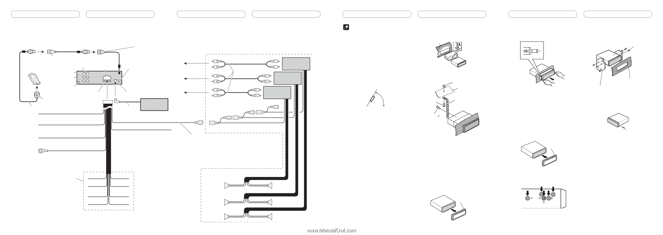
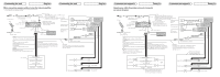
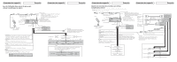
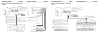
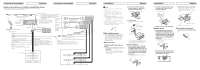
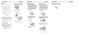
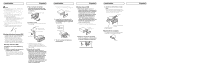
Conexión de las unidades Español Cuando conecte altavoces sin utilizar el amplificador interno • Cuando utilice este sistema, se recomienda apagar el amplificador interno de esta unidad. Para los detalles, consulte el manual de instrucciones. Conexión de las unidades Español 50 cm iPod Cable USB CD-U150E Pioneer (vendido separadamente) Salida trasera Salida delantera Salida de altavoz de subgraves Este producto Toma de antena Fusible (10 A) Conector del Dock Cable de interfaz Puerto USB 2 Utilice un cabo USB para conectar el dispositivo 20 cm de almacenamiento USB al puerto USB 2. El cable USB CD-U150E Pioneer también está disponible. Para los detalles, consulte su revendedor. Entrada remota por cable Es posible conectar un adaptador A la salida trasera de mando a distancia por cable (se vende por separado). A la salida delantera Entrada IP-BUS (Azul) Reproductor de Multi-CD (vendido Cable IP-BUS separadamente) A la salida del altavoz de subgraves Conecte los cables RCA (vendidos separadamente) Amarillo Conecte el terminal de suministro de 12 V constante. Rojo Conecte al terminal controlado por del interruptor de encendido (12 V CC). Anaranjado/blanco Conecte al terminal de interruptor de iluminación. Negro (masa de la carrocería) Conecte a un punto de metal limpio, libre de pintura. Amarillo/negro Si se utiliza un equipo con función de silenciamiento, conecte este conductor con el conductor de silenciamiento de audio en tal equipo. De lo contrario, mantenga el conductor de silenciamiento de audio libre de conexiones. Control remoto de sistema Azul/blanco Conecte al terminal de control de sistema del amplificador de potencia o al terminal de control de relé de antena automática (máx. 300 mA 12 V CC). Amplificador de potencia (vendido separadamente) Amplificador de potencia (vendido separadamente) Amplificador de potencia (vendido separadamente) No se usa. Blanco Gris Blanco/negro Verde Gris/negro Violeta Verde/negro Violeta/negro Altavoz de subgraves Altavoz delantero Altavoz trasero Altavoz de subgraves Altavoz delantero Altavoz trasero Installation Note • Check all connections and systems before final installation. • Do not use unauthorized parts. The use of unauthorized parts may cause malfunctions. • Consult with your dealer if installation requires drilling of holes or other modifications of the vehicle. • Do not install this unit where: - it may interfere with operation of the vehicle. - it may cause injury to a passenger as a result of a sudden stop. • The semiconductor laser will be damaged if it overheats. Install this unit away from hot places such as near the heater outlet. • Optimum performance is obtained when the unit is installed at an angle of less than 60°. 60° DIN Front/Rear-mount This unit can be properly installed either from "Front" (conventional DIN Front-mount) or "Rear" (DIN Rear-mount installation, utilizing threaded screw holes at the sides of unit chassis). For details, refer to the following installation methods. DIN Front-mount Installation with metal strap and screws 1. Insert the mounting sleeve into the dashboard. • When installing in a shallow space, use a supplied mounting sleeve. If there is enough space behind the unit, use factory supplied mounting sleeve. English 2. Secure the mounting sleeve by using a screwdriver to bend the metal tabs (90°) into place. Dashboard Mounting sleeve 182 53 3. Install the unit. • Use commercially available parts when installing. Nut Firewall or metal support Screw Metal strap Screw (M4˜8) • Make sure that the unit is installed securely in place. Unstable installation may cause this unit to malfunction, such as sound skip. Removing the Unit 1. Extend top and bottom of the trim ring outwards to remove the trim ring. When reattaching the trim ring, push the trim ring onto the unit until it clicks. (If the trim ring is attached upside down, the trim ring will not fit properly.) • It becomes easy to remove the trim ring if the front panel is released. Trim ring Installation 2. Insert the supplied extraction keys into both sides of the unit until they click into place. English 3. Tighten two screws on each side. • Use either truss screws (5 mm × 8 mm) or flush surface screws (5 mm × 9 mm), depending on the shape of screw holes in the bracket. Screw 3. Pull the unit out of the dashboard. DIN Rear-mount 1. Extend top and bottom of the trim ring outwards to remove the trim ring. When reattaching the trim ring, push the trim ring onto the unit until it clicks. (If the trim ring is attached upside down, the trim ring will not fit properly.) • It becomes easy to remove the trim ring if the front panel is released. Dashboard or Console Factory radio mounting bracket Fastening the front panel If you do not plan to detach the front panel, the front panel can be fastened with supplied screw. Screw Trim ring 2. Determine the appropriate position where the holes on the bracket and the side of the unit match.
-
 1
1 -
 2
2 -
 3
3 -
 4
4 -
 5
5 -
 6
6 -
 7
7 -
 8
8
 |
 |