Pioneer DEH-P6200BT Installation Manual - Page 5
Installation, English - installation support
 |
UPC - 884938103145
View all Pioneer DEH-P6200BT manuals
Add to My Manuals
Save this manual to your list of manuals |
Page 5 highlights
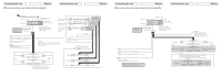
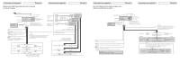
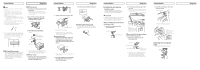
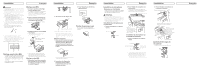
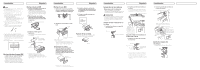
Installation English Note • Check all connections and systems before final installation. • Do not use unauthorized parts. The use of unauthorized parts may cause malfunctions. • Consult with your dealer if installation requires drilling of holes or other modifications of the vehicle. • Do not install this unit where: - it may interfere with operation of the vehicle. - it may cause injury to a passenger as a result of a sudden stop. • The semiconductor laser will be damaged if it overheats. Install this unit away from hot places such as near the heater outlet. • Optimum performance is obtained when the unit is installed at an angle of less than 60°. 60° • When installing, to ensure proper heat dispersal when using this unit, make sure you leave ample space behind the rear panel and wrap any loose cables so they are not blocking the vents. Leave ample space Dashboard 10 cm DIN Front-mount 1. Insert the mounting sleeve into the dashboard. • When installing in a shallow space, use a supplied mounting sleeve. If there is enough space behind the unit, use factory supplied mounting sleeve. 2. Secure the mounting sleeve by using a screwdriver to bend the metal tabs (90°) into place. Dashboard Mounting sleeve 182 53 3. Install the unit as illustrated. • Use commercially available parts when installing. Nut Firewall or metal support Screw Metal strap 10 cm Screw (M4˜8) DIN Front/Rear-mount This unit can be properly installed either from "Front" (conventional DIN Front-mount) or "Rear" (DIN Rear-mount installation, utilizing threaded screw holes at the sides of unit chassis). For details, refer to the following installation methods. • Make sure that the unit is installed securely in place. Unstable installation may cause this unit to malfunction, such as sound skip. DIN Rear-mount 1. Determine the appropriate position where the holes on the bracket and the side of the unit match. Installation English 3. Pull the unit out of the dashboard. 2. Tighten two screws on each side. Screw Dashboard or Console Factory radio mounting bracket • Use either truss (5 mm × 8 mm) or flush surface (5 mm × 9 mm) screws, depending on the bracket screw holes. Removing the Unit 1. Extend top and bottom of the trim ring outwards to remove the trim ring. (When reattaching the trim ring, point the side with the groove down.) Fastening the front panel If you do not plan to detach the front panel, the front panel can be fastened with supplied screw. Screw Trim ring • Releasing the front panel allows easier access to the trim ring. 2. Insert the supplied extraction keys into both sides of the unit until they click into place. Installation English Installing the microphone Installation notes Install the microphone in a position and orientation that will enable it to pick up the voice of the person operating the system. CAUTION • It is extremely dangerous to allow the microphone lead to become wound around the steering column or gearstick. Be sure to install the unit in such a way that it will not obstruct driving. When installing the microphone on the sun visor 1. Install the microphone on the microphone clip. Microphone Microphone clip 2. Install the microphone clip on the sun visor. • With the sun visor up, install the microphone clip. (Lowering the sun visor reduces the voice recognition rate.) Microphone clip Clamp Use separately sold clamps to secure the lead where necessary inside the vehicle. When installing the microphone on the steering column 1. Install the microphone on the microphone clip. Microphone Microphone base Microphone clip Fit the microphone lead into the groove. • Microphone can be installed without using microphone clip. In this case, detach the microphone base from the microphone clip. To detach the microphone base from microphone clip, slide the microphone base. Installation 2. Install the microphone clip on the steering column. Double-sided tape Install the microphone clip on the rear side of the steering column. Clamp Use separately sold clamps to secure the lead where necessary inside the vehicle. Adjusting the microphone angle The microphone angle can be adjusted. English
-
 1
1 -
 2
2 -
 3
3 -
 4
4 -
 5
5 -
 6
6 -
 7
7 -
 8
8
 |
 |
