Pioneer DEX-P1R Connection Guide
Pioneer DEX-P1R Manual
 |
View all Pioneer DEX-P1R manuals
Add to My Manuals
Save this manual to your list of manuals |
Pioneer DEX-P1R manual content summary:
- Pioneer DEX-P1R | Connection Guide - Page 1
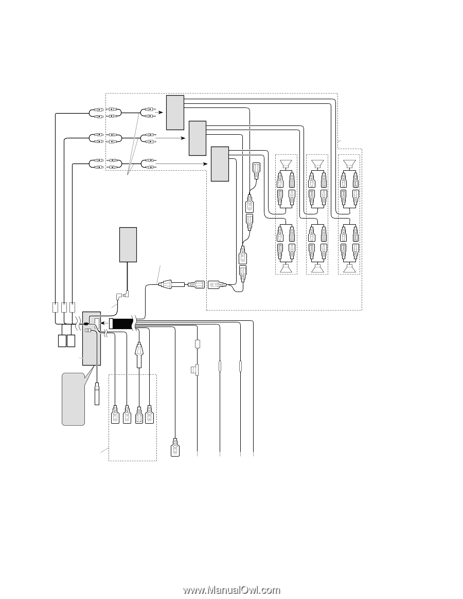
DEX-P1R,DEH-P946,DEX-P1 128 - Connection Diagram (DEX-P1/ES) Small inverter units Switch the PRO/STD Switch PRO or STD. This Product See the section "DFS Alarm Installation". Antenna jack White/orange White/red Brown White Fuse holder Yellow/black If you use a cellular telephone, connect it - Pioneer DEX-P1R | Connection Guide - Page 2
DEX-P1R,DEH-P946,DEX-P1 Key Finder Head Unit +/- button OPEN/EJECT button SOURCE/OFF button ' ' S/A button FS button [/] button CLOCK button DISPLAY button '/ button Remote Controller RT button '/ button DISPLAY button CD button ANGLE button ATT button Buttons 1- 6 +/- button DSP button [/] - Pioneer DEX-P1R | Connection Guide - Page 3
DEX-P1R,DEH-P946,DEX-P1 130 Tuner Operation Basic Operation of Tuner 1. Select Tuner. Each press changes the Source ... The program service name or frequency appears on the display. 2. Select the desired band. FM1 → FM2 → FM3 → AM 3. Tune the receiver to a higher or lower frequency. "RDS" " - Pioneer DEX-P1R | Connection Guide - Page 4
DEX-P1R,DEH-P946,DEX-P1 131 Using United States and in some parts display. Note: • The RDS service does not provide AM broadcast information. • The RDS service may not be provided by all FM stations. • Sections 1 and 2 provide explanations concerning menus for RDS/ID LOGIC operations the mode in - Pioneer DEX-P1R | Connection Guide - Page 5
-P1R,DEH-P946,DEX-P1 132 Using RDS/ID LOGIC 4. Select the state. States are stored alphabetically. 5. Advance to next selection. 6. Using the APS (Auto Position Setting) function, automatically set the city the vehicle is located in. When you have completed APS, the city name flashes in the display - Pioneer DEX-P1R | Connection Guide - Page 6
DEX-P1R,DEH-P946,DEX-P1 133 Using the "Format" station selection mode. "FRMT" Each press of the FS button changes the method in operation 3 during reception of a broadcast station with no format data, "NO FORMAT" is displayed. The tuner then returns to the prior frequency. • "NO STATION" is displayed - Pioneer DEX-P1R | Connection Guide - Page 7
DEX-P1R,DEH-P946,DEX-P1 134 Using Display Modes This function can be used to scroll through the various display modes for Call Sign, Program Service Name and Format. • Select the desired display mode. Each press changes the Display ... Each press changes the Display ... Each press of the DISPLAY - Pioneer DEX-P1R | Connection Guide - Page 8
DEX-P1R,DEH-P946,DEX-P1 135 Using RDS/ID LOGIC 8. TA Function The TA (Traffic uses RDS service data, so it does not operate during AM recep- tion. Activating/Deactivating the TA Function 1. Tune in a TP station. The "TP" indicator lights when the tuner is tuned to a TP station. 2. Select the TA mode - Pioneer DEX-P1R | Connection Guide - Page 9
DEX-P1R,DEH-P946,DEX-P1 136 Using RDS/ID LOGIC 9. PTY Alarm The PTY Alarm function automatically player mode, the tuner automatically seeks out the RDS station with the strongest signal in the current area 10 seconds after RDS station reception has become impossible. (This function does not operate - Pioneer DEX-P1R | Connection Guide - Page 10
Using RDS/ID LOGIC 11. Multi-Station When "MS" is displayed, this indicates there are a number of the APF ON/OFF mode (SET APF) in the Detailed Setting Menu. 2. Switch APF ON or OFF. To cancel the Detailed Setting Menu, press the BAND button. DEX-P1R,DEH-P946,DEX-P1 137 Pressing the button - Pioneer DEX-P1R | Connection Guide - Page 11
DEX-P1R,DEH-P946,DEX-P1 138 Using the Built-in CD Player Basic Operation of the Built-in CD Player The built-in CD player plays one standard 12 cm or 8 cm (single) CD at a time. Do not use an adapter when playing an 8 cm CD. 1. Open the front panel and insert the disc with the label - Pioneer DEX-P1R | Connection Guide - Page 12
DEX-P1R,DEH-P946,DEX-P1 139 Using the Built-in CD Player Scrolling the Display This unit displays the first 10 letters only of Disc Title, Artist Name and Track Title. With text longer than 10 letters, you can see the rest of the text by scrolling. • Scroll the display. Hold for 2 seconds Hold - Pioneer DEX-P1R | Connection Guide - Page 13
DEX-P1R,DEH-P946,DEX-P1 140 Using Multi-CD Players 4. Raise or lower the volume. 5. Turn the source OFF. Hold for 1 second Each press changes the Source ... Playing Discs on a 50-Disc - Pioneer DEX-P1R | Connection Guide - Page 14
-6, -12, -18 dB/oct Level: +6 - -24 dB (1 dB) Phase: Normal/Reverse Network (PRO Mode) High ...... HPF frequency: 2 k, 2.5 k, 3.15 k, 4 k, 5 k, 6.3 k, 8 k, Note: • Specifications and the design are subject to possi- ble modification without notice due to improvements. DEX-P1R,DEH-P946,DEX-P1 141 - Pioneer DEX-P1R | Connection Guide - Page 15
DEX-P1R,DEH-P946,DEX-P1 - DEH-P946/ES, DEX-P1/ES General Power source .......... 14.4 V DC (10.8 - 15.1 V allowable) Grounding system Negative type Max. current consumption (DEH-P946/ES 10 A Max. current consumption (DEX-P1 ) Phase: Normal/Reverse Network (PRO Mode) High ...... HPF frequency: 2
-
 1
1 -
 2
2 -
 3
3 -
 4
4 -
 5
5 -
 6
6 -
 7
7 -
8
-
9
-
10
-
11
-
12
-
13
-
14
-
15
 |
 |
128
DEX-P1R,DEH-P946,DEX-P1
-
Connection Diagram (DEX-P1/ES)
Multi-CD player
(sold separately)
Power amp
(sold separately)
Power amp
(sold separately)
Power amp
(sold separately)
Orange
To terminal always supplied with power
regardless of ignition switch position.
Red
To electric terminal controlled by ignition
switch (12 V DC) ON/OFF.
Yellow
To light switch terminal.
Black (ground)
To vehicle (metal) body.
Antenna jack
Brown
White
Yellow/black
If you use a cellular telephone, connect it via
the Audio Mute lead on the cellular telephone.
If not, keep the Audio Mute lead free of any
connections.
Fuse holder
Fuse resistor
Fuse resistor
Blue
To system control terminal of the power
amp or Auto-antenna relay control
terminal.
(Max. 300 mA 12 V DC)
White/red
White/orange
See the section “DFS Alarm
Installation”.
White label (MID/FRONT OUTPUT)
Green label (HIGH/REAR OUTPUT)
Black label (LOW/SUBWOOFER OUTPUT)
IP-BUS cable
This Product
Small inverter units
Fuse holder
Fuse holder
Connecting cords
with RCA pin plugs
(sold separately)
Left speaker
Use this for connections when
you have the separately
available amplifier.
Blue
PRO: Middle
STD: Front
Blue
Blue
Right speaker
PRO: High
STD: Rear
PRO: Low
STD: Subwoofer
Switch the PRO/STD Switch
PRO or STD.