Pioneer DJM-500 Owner's Manual
Pioneer DJM-500 Manual
 |
View all Pioneer DJM-500 manuals
Add to My Manuals
Save this manual to your list of manuals |
Pioneer DJM-500 manual content summary:
- Pioneer DJM-500 | Owner's Manual - Page 1
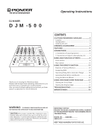
Operating Instructions DJ MIXER DJM-500 Thank you for buying this Pioneer product. Please read through these operating instructions so you will know how to operate your model properly. After you have finished reading the instructions, put them away in a safe place for future reference. CONTENTS - Pioneer DJM-500 | Owner's Manual - Page 2
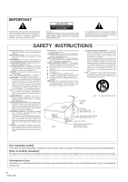
COVER (OR BACK). NO USER-SERVICEABLE PARTS INSIDE. REFER SERVICING TO QUALIFIED SERVICE PERSONNEL. The exclamation point within an equilateral triangle is intended to alert the user to the presence of important operating and maintenance (servicing) instructions in the literature accompanying the - Pioneer DJM-500 | Owner's Manual - Page 3
pursuant to Part 15 of the FCC Rules. These limits are designed to provide reasonable protection against harmful interference in a residential installation. This equipment generates, uses, and can radiate radio frequency energy and, if not installed and used in accordance with the instructions, may - Pioneer DJM-500 | Owner's Manual - Page 4
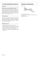
form inside, and the unit may not be able to attain its full performance. In cases like this, allow the unit to stand for about an hour or raise the room temperature gradually. Cleaning the unit • Use a polishing cloth to wipe off dust and dirt. • When the surfaces are very dirty, wipe - Pioneer DJM-500 | Owner's Manual - Page 5
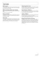
master. A variety of effects such as delay, echo, auto pan, flanger, reverb, and pitch shifter can be enjoyed. Enhanced Input/Output Terminals In addition to the 9 inputs, 2 CD and 2 LINE systems, 3 PHONO (for MM only) systems, and 2 microphone systems, three outputs including the pro-specifications - Pioneer DJM-500 | Owner's Manual - Page 6
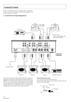
LINE L L CH - 2 PHONO 1 CD 2 / LINE CH - 1 LINE CD 1 L L R R R MASTER LEVEL ATT. R SIGNAL GND R CH - 2 CH - 1 PLAYER CONTROL ~AC IN R MASTER OUT 2 R LR LR L CH - 4 L MASTER OUT 3 SEND (MONO) RETURN (MONO) SUBMIC DJM-500 before after use. Connecting audio cords Use cords - Pioneer DJM-500 | Owner's Manual - Page 7
Pin assignment *1 DJM-500 COLD (-) 23 1 HOT (+) GND Power amplifier Power amplifier External effector (Supporting XLR input) (Supporting PHONE input) *1 Master level attenuator knob To protect the connected amplifiers and speakers from excessive inputs, this knob is used to decrease the - Pioneer DJM-500 | Owner's Manual - Page 8
PARTS Front section 1 2 3 45 8 9 0 - = MIC CH-1 CD 1/LINE LINE PROFESSIONAL CH-2 CH-3 DJ MIXER DJM-500 CH-4 MASTER CD 2/LINE PHONO 1 LINE 4 ON OFF FADER START ON CROSS FADER OFF ON 23 1 4 PHONES ASSIGN A CROSS FADER ASSIGN B MASTER EFFECT 10 10 EFFECT SELECTOR 9 9 - Pioneer DJM-500 | Owner's Manual - Page 9
fader. The display range is about -24 dB to +14 dB. When BPM is selected using the effect selector and the effect switch is turned on, the beat monitor function will be turned on. 3 Master Output Monaural/Stereo Selection Switch (MONO/STEREO) NAME AND FUNCTION OF PARTS 4 Master level meter (MASTER - Pioneer DJM-500 | Owner's Manual - Page 10
Master Balance Knob (MASTER BALANCE) Used to adjust the left and right balance of the master output. & Booth Monitor Level Knob (BOOTH MONITOR LEVEL) Used to adjust the output level of the BOOTH MONITOR terminal. Not affected by the master volume and master balance. * Effect Selector Switch (EFFECT - Pioneer DJM-500 | Owner's Manual - Page 11
speaker for monitoring audio. 3 Master Output Level Adjustment Knob (MASTER LEVEL ATT.) 4 CH-4 Phono Input Terminal (PHONO 3) PHONO 3 : Connects the analog player. (for MM only) 5 CH-3 Input Terminal PHONO 2 : Connects the analog player. (for MM only) LINE : Connects audio equipment such as - Pioneer DJM-500 | Owner's Manual - Page 12
USING THE EFFECT FUNCTION With the built-in DSP (digital signal processor), sound effects can be enjoyed and BPM measured. Monitor selector (Auto BPM Counter Selector) MIC CH-1 CD 1/LINE LINE PROFESSIONAL CH-2 CH-3 DJ MIXER DJM-500 CH-4 MASTER CD 2/LINE PHONO 1 LINE PHONO 2 SUB MIC - Pioneer DJM-500 | Owner's Manual - Page 13
USING THE EFFECT FUNCTION 2. Echo (repeated sounds) Mixes echo sounds of 1/2, 3/4, and 1/1 beats quickly and simply. For example, when input sounds are cut with the 1/1 beat echo sound, the song fades out while repeating sounds corresponding to the beat. When the microphone sound is imposed - Pioneer DJM-500 | Owner's Manual - Page 14
BPM counter selector) and channel selected using the effect channel selector is measured and displayed. (Example) Displays the BPM of the song input to the monitor selector CH2 and effect channel selector CH4. 1 Set the effect selector to AUTO BPM. 2 Set the effect channel selector to CH4. • The - Pioneer DJM-500 | Owner's Manual - Page 15
with the parameter knob (delay time USING THE EFFECT FUNCTION 1234 AUTO BPM COUNTER REAL AVERAGE mSec MASTER 1 2 3 4 MIC PARAMETER BPM 1/2 3/4 1/1 2/1 4/1 BEAT Display where a half beat delay (250 mSec) has been set to the music with BPM of 120 (time conversion 500 mSec.) Precautions for Effect - Pioneer DJM-500 | Owner's Manual - Page 16
parameter knob. • To check the effect sound, press the effect of the monitor selector. This will enable the effect sound to be monitored using the headphone and booth monitor outputs. 4 Turn on the effect switch. • The effect switch blinks and the effect (pitch shift) is imposed on the master output - Pioneer DJM-500 | Owner's Manual - Page 17
MIC 1 MASTER MASTER BALANCE PARAMETER L R BOOTH MONITOR LEVEL MIN MAX EFFECT ON/OFF -∞ 0dB Cross fader switch Assign (B) switch Cross fader control Fader Start Play When the DJ mixer DJM-500 and the CD player CDJ-500G for DJs are connected using the control cable, fader start - Pioneer DJM-500 | Owner's Manual - Page 18
from the unit, and disconnect the connector D. 5 Remove the two screws E and replace the cross fader volume control with a new one. 6 Attach the screws E, connector D, slider panel C, screws B, and knob A of the cross fader in the reverse order of the above. Fully insert the connector D into the - Pioneer DJM-500 | Owner's Manual - Page 19
SPECIFICATIONS Audio Section Input terminal (Input level/impedance) CD/LINE 14 dBV (200 mV) / 22 kΩ PHONO 54 dBV (2 mV) / 47 kΩ MAIN MIC 54 dBV (2 mV) / 3 kΩ SUB MIC 60 dBV (1 mV) / 3 kΩ RETURN 14 dBV (200 mV) / 22 kΩ Output terminal (Output level/impedance) MASTER OUT 1 (RCA 0 dBV (1 V) / 1 - Pioneer DJM-500 | Owner's Manual - Page 20
ELECTRONIC CORPORATION 4-1, Meguro 1-Chome, Meguro-ku, Tokyo 153, Japan PIONEER NEW MEDIA TECHNOLOGIES, INC. 2265 East 220th Street, Long Beach, California 90810, U.S.A. PIONEER ELECTRONICS OF CANADA, INC. 300 Allstate Parkway, Markham, Ontario L3R OP2, Canada Printed in Japan
-
 1
1 -
 2
2 -
 3
3 -
 4
4 -
 5
5 -
 6
6 -
 7
7 -
8
-
9
-
10
-
11
-
12
-
13
-
14
-
15
-
16
-
17
-
18
-
19
-
20
 |
 |

Operating Instructions
DJM-500
DJ MIXER
IMPORTANT NOTICE:
RECORD THE MODEL NUMBER AND SERIAL NUMBER
OF THIS EQUIPMENT BELOW. THE NUMBERS ARE ON
THE REAR PANEL.
MODEL NO.
DJM-500
SERIAL NO.
KEEP THESE NUMBERS FOR FUTURE USE.
WARNING
:
TO PREVENT FIRE OR SHOCK HAZARD, DO
NOT EXPOSE THIS APPLIANCE TO RAIN OR MOISTURE.
CAUTION:
This product satisfies FCC regulations when
shielded cables and connectors are used to connect the unit to
other equipment. To prevent electromagnetic interference with
electric appliances such as radios and televisions, use shielded
cables and connectors for connections.
Thank you for buying this Pioneer product.
Please read through these operating instructions so you
will know how to operate your model properly.
After you have finished reading the instructions, put them
away in a safe place for future reference.
CONTENTS
CAUTIONS REGARDING HANDLING
...............
4
Location
....................................................................
4
Condensation
...........................................................
4
Cleaning the unit
.....................................................
4
CHECKING ACCESSORIES
................................
4
FEATURES
...........................................................
5
CONNECTIONS
...................................................
6
1. Connection of Input Equipment
.........................
6
2. Connection of Outputs, Microphones, Etc
. .......
7
NAME AND FUNCTION OF PARTS
...................
8
Front section
............................................................
8
Rear section
...........................................................
11
USING THE EFFECT FUNCTION
......................
12
Features of Various Effectors
................................
12
Measuring BPM
.....................................................
14
Operating Delay, Echo, Auto pan, Flanger
..........
15
Operating Pitch Shifter and Reverb
.....................
16
Using the External Effecter
...................................
16
USING THE FADER START FUNCTION
..........
17
Starting the Cross Fader
.......................................
17
Starting the Channel fader
....................................
17
TROUBLESHOOTING
.......................................
18
SPECIFICATIONS
..............................................
19