Pioneer DJM-500 Owner's Manual - Page 6
Connections - master att
 |
View all Pioneer DJM-500 manuals
Add to My Manuals
Save this manual to your list of manuals |
Page 6 highlights
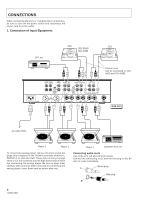
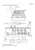
CONNECTIONS When connecting the units or changing their connections, be sure to turn off the power switch and disconnect the power cord from the outlet. 1. Connection of Input Equipment DAT, etc. CD2 CD1 CDJ-500G/ CDJ-500 Control cord Can be connected to CDJ500G and CDJ-500 . L R L R MASTER BOOTH OUT 1 MONITOR L CH - 4 PHONO 3 CH - 3 PHONO 2 LINE L L CH - 2 PHONO 1 CD 2 / LINE CH - 1 LINE CD 1 L L R R R MASTER LEVEL ATT. R SIGNAL GND R CH - 2 CH - 1 PLAYER CONTROL ~AC IN R MASTER OUT 2 R LR LR L CH - 4 L MASTER OUT 3 SEND (MONO) RETURN (MONO) SUBMIC DJM-500 L R L R L R L R L R AC 120V, 60Hz Player 3 Player 2 Player 1 Cassette deck, etc. To connect the analog player, remove the short-circuit pin plugs (four) inserted in the PHONO terminals (PHONO 1, PHONO 2) of CH2 and CH3. These short-circuit pin plugs serve to cut fine noises to provide high performance when not connecting the analog player. Be sure to keep them carefully after removal. When removed for connecting the analog player, insert them back as before after use. Connecting audio cords Use cords with red and white pin plugs. Connect the white plug to (L) and the red plug to (R). Be sure to insert completely. White plug L Red plug R 6
-
 1
1 -
 2
2 -
 3
3 -
 4
4 -
 5
5 -
 6
6 -
 7
7 -
 8
8 -
 9
9 -
 10
10 -
 11
11 -
 12
12 -
13
-
14
-
15
-
16
-
17
-
18
-
19
-
20
 |
 |
