Pioneer FM903XM Installation Manual
Pioneer FM903XM - Satellite Radio Tuner Manual
 |
UPC - 012562566009
View all Pioneer FM903XM manuals
Add to My Manuals
Save this manual to your list of manuals |
Pioneer FM903XM manual content summary:
- Pioneer FM903XM | Installation Manual - Page 1
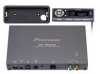
MANUAL GEX-FM903XM This product conforms to CEMA cord colors. Connecting the Units Note: • This unit is for vehicles with a 12-volt battery and negative grounding. Before installing it in a recreational vehicle, truck, or bus, check the battery voltage. • To avoid shorts in the electrical system - Pioneer FM903XM | Installation Manual - Page 2
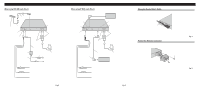
using ADD ON mode (Fig. 2) 5.5 m 1m Control Unit Antenna Input This Unit Power Supply Green (Terrestrial) Yellow (Satellite) 5.7 m Antenna switching unit 50 cm Car antenna plug Antenna Unit (AN-90XM) (sold separately) To FM car radio Fuse holder Fuse resistor Yellow To terminal always - Pioneer FM903XM | Installation Manual - Page 3
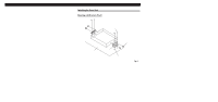
the unit and the system work properly. • Use only the parts included with the unit to ensure proper installation. The use of unauthorized the mechanism and cause a short circuit. Installing the Tuner Unit Mounting with Brackets (Fig. 6) Tapping screw (4 × 12 mm) Car mat or chassis Screw (4 × 6 - Pioneer FM903XM | Installation Manual - Page 4
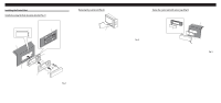
unit (Fig. 8) Insert the release plate that comes with the unit as shown in the illustration. Pull it towards you. Fig. 8 Open the installation hole. Holder Screws Fig. 7 Fasten the control unit with velcro tape (Fig. 9) Velcro tape (Rough surface) Dashboard Velcro tape (Soft surface) Fig
-
 1
1 -
 2
2 -
 3
3 -
 4
4
 |
 |
INSTALLATION MANUAL
INSTALLATION MANUAL
<KYMFZ/01G00000>
GEX-FM903XM
Printed in Japan
<CRB1737-A> UC
Connecting the Units
Note:
•
This unit is for vehicles with a 12-volt battery and
negative grounding. Before installing it in a recre-
ational vehicle, truck, or bus, check the battery
voltage.
•
To avoid shorts in the electrical system, be sure to
disconnect the
≠
battery cable before beginning
installation.
•
Refer to the owner’s manual for details on
connecting the power amp and other units, then
make connections correctly.
•
Secure the wiring with cable clamps or adhesive
tape. To protect the wiring, wrap adhesive tape
around them where they lie against metal parts.
•
Route and secure all wiring so it cannot touch any
moving parts, such as the gear shift, handbrake and
seat rails. Do not route wiring in places that get
hot, such as near the heater outlet. If the insulation
of the wiring melts or gets torn, there is a danger of
the wiring short-circuiting to the vehicle body.
•
Don’t pass the yellow lead through a hole into the
engine compartment to connect to the battery. This
will damage the lead insulation and cause a very
dangerous short.
•
Do not shorten any leads. If you do, the protection
circuit may fail to work when it should.
•
Never feed power to other equipment by cutting
the insulation of the power supply lead of the unit
and tapping into the lead. The current capacity of
the lead will be exceeded, causing overheating.
•
When replacing fuse, be sure to use only fuse of
the rating prescribed on the fuse holder.
•
To prevent incorrect connection, the input side of
the IP-BUS connector is blue, and the output side
is black. Connect the connectors of the same
colors correctly.
•
If this unit is installed in a vehicle that does not
have an ACC (accessory) position on the ignition
switch, the red lead of the unit should be connected
to a terminal coupled with ignition switch ON/OFF
operations. If this is not done, the vehicle battery
may be drained when you are away from the vehi-
cle for several hours. (Fig.1)
Fig. 1
No ACC position
ACC position
O
N
S
T
A
R
T
O
F
F
A
C
C
O
N
S
T
A
R
T
O
F
F
This product conforms to CEMA cord colors.
•
Cords for this product and those for other products
may be different colors even if they have the same
function. When connecting this product to another
product, refer to the supplied Installation manuals
of both products and connect cords that have the
same function.