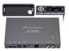
Pioneer FM903XM Installation Manual - Page 2
Connecting the Units - antenna
 |
UPC - 012562566009
View all Pioneer FM903XM manuals
Add to My Manuals
Save this manual to your list of manuals |
Page 2 highlights
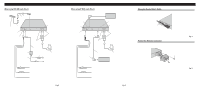
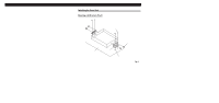
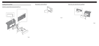
Connecting the Units When using ADD ON mode (Fig. 2) 5.5 m 1m Control Unit Antenna Input This Unit Power Supply Green (Terrestrial) Yellow (Satellite) 5.7 m Antenna switching unit 50 cm Car antenna plug Antenna Unit (AN-90XM) (sold separately) To FM car radio Fuse holder Fuse resistor Yellow To terminal always supplied with power regardless of ignition switch position. Red To electric terminal controlled by ignition switch (12 V DC) ON/OFF. Black (ground) To vehicle (metal) body. Fig. 2 When using IP-BUS mode (Fig. 3) IP-BUS Input (Blue) Power Supply Multi-CD player (sold separately) IP-BUS Output (Black) Antenna Input This Unit Black Green (Terrestrial) Yellow (Satellite) To IP-BUS Input (Blue) IP-BUS cable (sold separately) Head Unit (sold separately) Antenna Unit (AN-90XM) (sold separately) Fuse holder Fuse resistor Yellow To terminal always supplied with power regardless of ignition switch position. Red To electric terminal controlled by ignition switch (12 V DC) ON/OFF. Black (ground) To vehicle (metal) body. Fig. 3 Clamp the Control Unit's Cable Clamper Fig. 4 Protect the Antenna Connector Screw (3 × 6 mm) Fig. 5
-
 1
1 -
 2
2 -
 3
3 -
 4
4
 |
 |
