Pioneer GM-X424 Service Manual - Page 19
Connecting, The Power Terminal, The Speaker Terminals
 |
View all Pioneer GM-X424 manuals
Add to My Manuals
Save this manual to your list of manuals |
Page 19 highlights
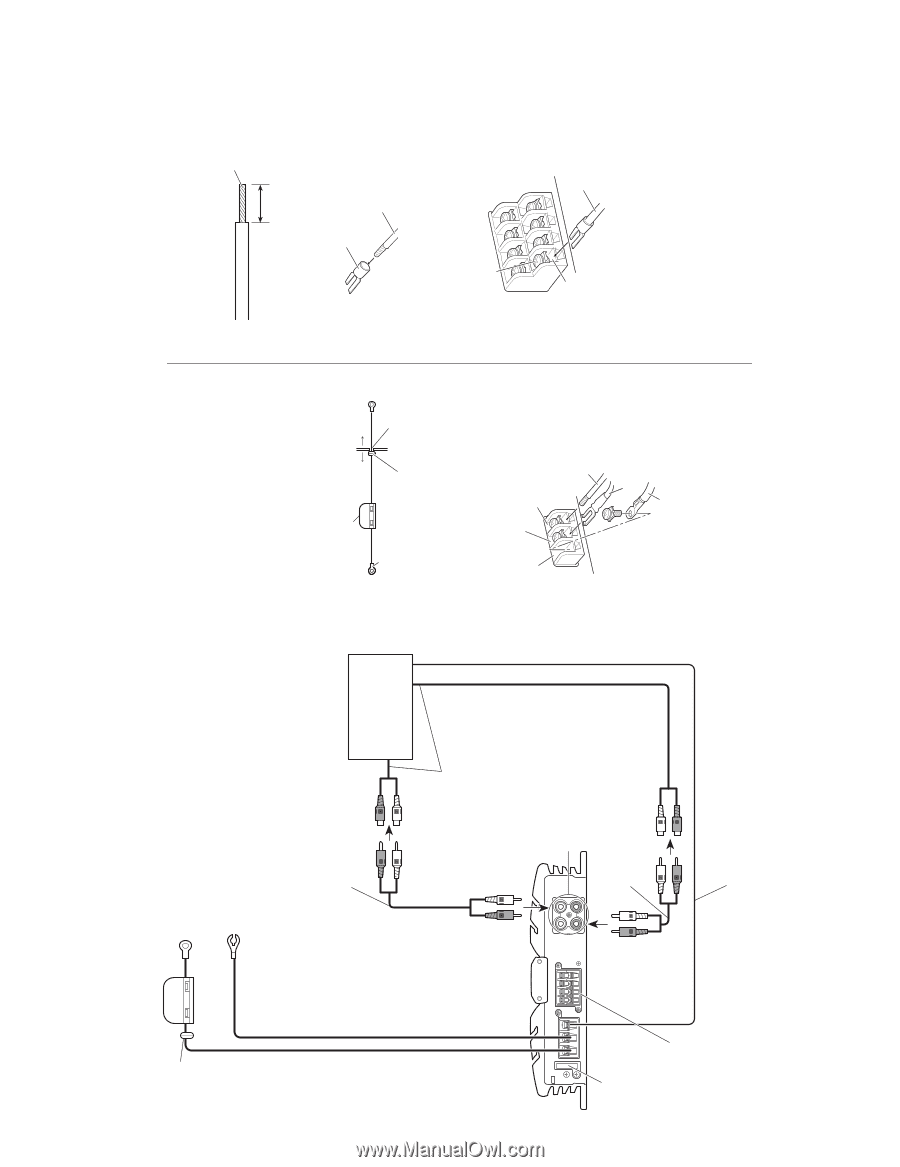
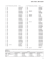
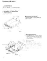
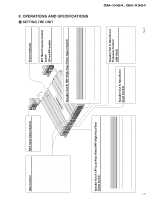
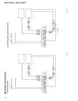
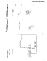
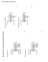
GM-X424, GM-X324 19 (3) GM-X324/X1R/UC Grommet Fuse (30 A) Fuse (25 A) Speaker output terminal See the "Connecting the Speakers and Input wires" section for speaker connection instructions. Special red battery wire [RD-222] (sold separately). After making all other connections at the amplifier, connect the battery wire terminal of the amplifier to the positive (+) terminal of the battery. Ground wire (black) [RD-222] (sold separately). Connect to metal body or chassis. Connecting wires with RCA pin plugs (sold separately). Car stereo with RCA output jacks External Output For details on how to connect to RCA input jacks A and B, see the "Connecting the Speakers and Input wires" section. If only input pin plug, do not connect anything to RCA input jack B. RCA input jack A, B Connecting wires with RCA pin plugs (sold separately). - CONNECTING - CONNECTING THE POWER TERMINAL THE SPEAKER TERMINALS • Be sure to use the special red battery wire supplied with the amplifier and connect directly to the battery. Use the supplied black ground wire and connect to the vehicle body. 1. Pass the battery wire from the engine compartment to the interior of the vehicle. • After making all other connections to the amplifier, connect the battery wire terminal of the amplifier to the positive (+) terminal of the battery. Engine Fuse (30A) compart- Interior of ment the vehicle 1. Expose the end of the speaker wires by about 10 mm and twist it using nippers or a cutter. Twist 10 mm 2. Attach lugs to speaker wire ends. • Use pliers, etc., to crimp lugs to wires. Lug Fig. 14 Positive terminal Insert the O-ring rubber grommet into the vehicle body. Drill an 8-mm hole into the vehicle body. Fig. 12 2. Connect the wires to the terminal. • Fix the wires securely with the terminal screws. GND terminal Power terminal System remote control terminal Speaker wire 3. Connect the speaker wires to the speaker output terminals. Fig. 15 • Fix the speaker wires securely with the terminal screws. Terminal screw System remote control wire (Blue) Speaker output terminal Speaker wire Ground wire Fig. 16 Blue Connect the male terminal of this wire to the blue wire of the car stereo (SYSTEM REMOTE CONTROL). The female terminal can be connected to the auto-antenna relay control terminal. If the car stereo does not have a system remote control terminal, connect the male terminal to the power terminal through the ignition switch. Fig. 11 Battery wire Fig. 13
-
 1
1 -
2
-
3
-
4
-
5
-
6
-
7
-
8
-
9
-
10
-
11
-
12
-
13
-
 14
14 -
 15
15 -
 16
16 -
 17
17 -
 18
18 -
 19
19 -
 20
20 -
 21
21
 |
 |