Pioneer GM-X424 Service Manual - Page 8
Pcb Connection Diagram
 |
View all Pioneer GM-X424 manuals
Add to My Manuals
Save this manual to your list of manuals |
Page 8 highlights
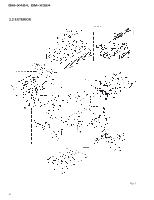
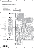
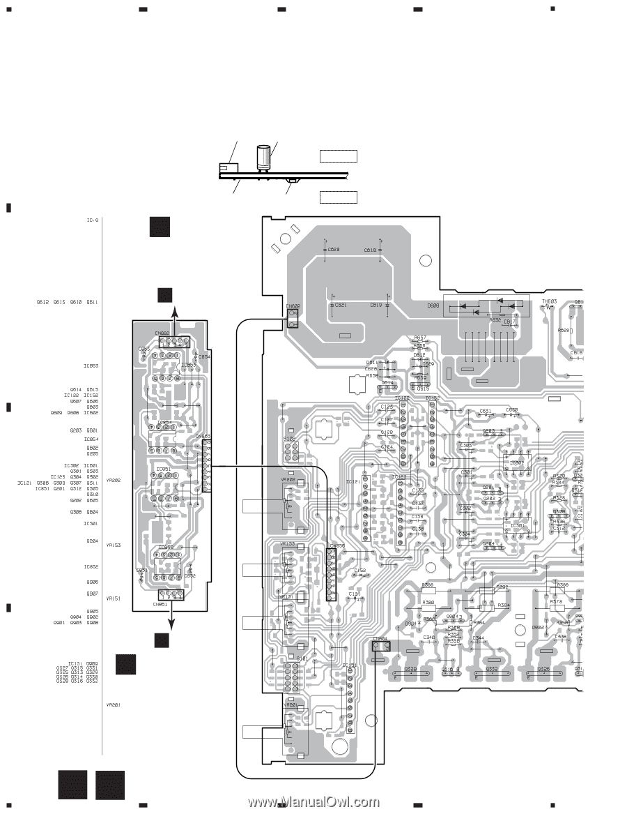
1 2 3 GM-X424, GM-X324 4. PCB CONNECTION DIAGRAM A NOTE FOR PCB DIAGRAMS 1. The parts mounted on this PCB 2. Viewpoint of PCB diagrams include all necessary parts for several destination. For further information for Connector Capacitor SIDE A respective destinations, be sure to check with the schematic diagram. P.C.Board Chip Part SIDE B ADJ A MOTHER PCB A CN854 B 4 G C A CN854 B ISOLATOR PCB D 8 AB 1 2 3 4
-
 1
1 -
2
-
 3
3 -
 4
4 -
 5
5 -
 6
6 -
 7
7 -
 8
8 -
 9
9 -
 10
10 -
 11
11 -
 12
12 -
 13
13 -
14
-
15
-
16
-
17
-
18
-
19
-
20
-
21
 |
 |
GM-X424, GM-X324
A
1
2
3
4
B
C
D
1
2
3
4
4. PCB CONNECTION DIAGRAM
Capacitor
Connector
P.C.Board
Chip Part
SIDE A
SIDE B
2. Viewpoint of PCB diagrams
B
8
A
ADJ
G
A
MOTHER PCB
A
CN854
A
CN854
B
ISOLATOR PCB
NOTE FOR PCB DIAGRAMS
1. The parts mounted on this PCB
include all necessary parts for
several destination.
For further information for
respective destinations, be sure
to check with the schematic dia-
gram.