Pioneer P4000 Other Manual - Page 3
Connecting the units, Installation - wiring
 |
UPC - 012562547978
View all Pioneer P4000 manuals
Add to My Manuals
Save this manual to your list of manuals |
Page 3 highlights
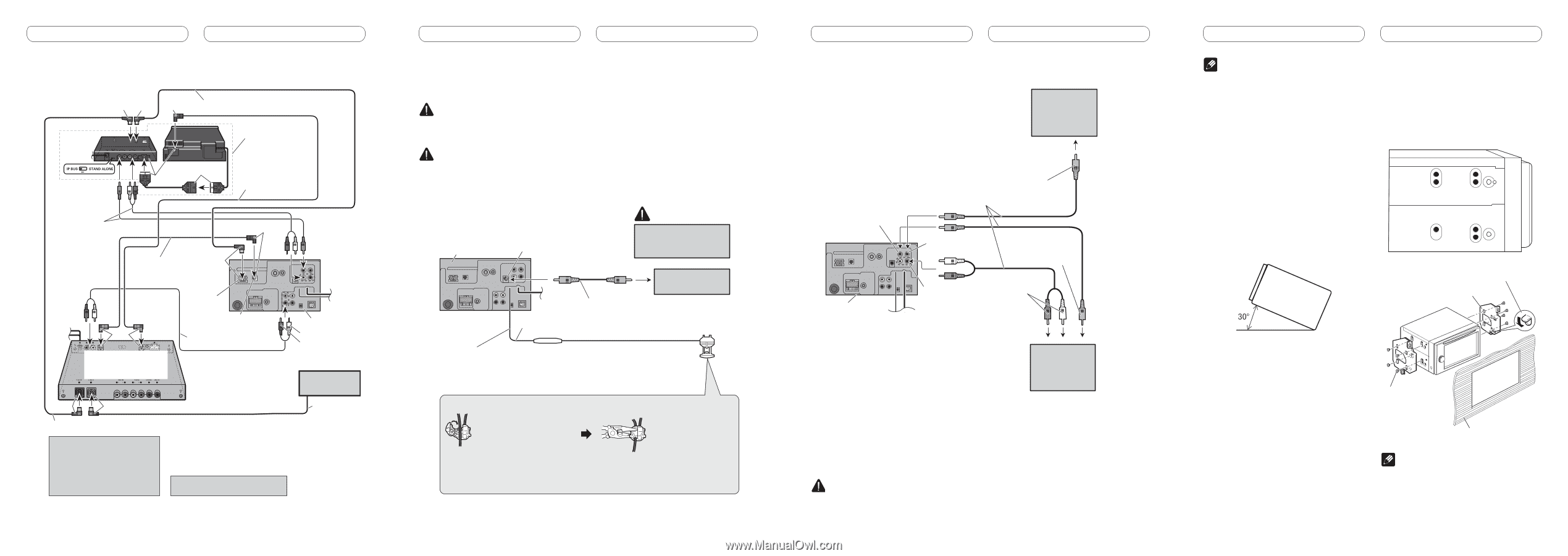
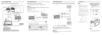
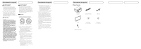
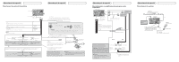
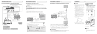
Connecting the units When connecting with a multi-channel processor Blue Black Black IP-BUS cable (supplied with DVD player) DVD player (e.g., XDV-P6) (sold separately) Black Black RCA cable (supplied with DVD player) Optical cable (sold separately) Black Optical cable (supplied with multi-channel processor) Blue Blue Multi-channel processor (e.g., DEQ-P8000) (sold separately) Black Blue IP-BUS cable (supplied with multi-channel processor) When you connect a separately sold DVD player to the separetely sold multi-channel processor, the optical cable from DVD player must be connected to the optical cable 2 input (OPT. IN2) of the multi-channel processor. IP-BUS input (Blue) Optical output (Black) RCA cable (supplied with multi-channel processor) You can use only one video component with this unit. This product To RL To RR Multi-CD player (sold separately) IP-BUS cable Connecting the units When connecting with a rear view camera When this product is used with a rear view camera, it is possible to automatically switch from the video to rear view image when the gear shift is moved to REVERSE (R). WARNING USE INPUT ONLY FOR REVERSE OR MIRROR IMAGE REAR VIEW CAMERA. OTHER USE MAY RESULT IN INJURY OR DAMAGE. CAUTION • The screen image may appear reversed. • The rear view camera function is to be used as an aid for backing into a tight parking spot. Do not use this function for entertainment purposes. • Objects in the rear view may appear closer or more distant than they actually are. This product Rear view camera input CAUTION You must use a camera which outputs mirror reversed images. To video output Rear view camera 15 cm (5-7/8 in.) RCA cable (sold separately) Violet/white Fuse resistor Of the two lead wires connected to the back lamp, connect the one in which the voltage changes when the gear shift is in the REVERSE (R) position. This connection enables the unit to sense whether the car is moving forwards or backwards. Connection method 1. Clamp the lead. 2. Clamp firmly with needle-nosed pliers. Note: · It is necessary to set CAMERA POLARITY properly in SYSTEM MENU when connecting the rear view camera. Connecting the units When connecting the external video component and the display Display with RCA input jacks (sold separately) Video input This product To video input RCA cables (sold separately) Rear monitor output To video output Audio input To audio outputs External video component (sold separately) • It is necessary to set AV INPUT to VIDEO in SYSTEM MENU when connecting the external video component. • It is necessary to set AV INPUT to S-DVD in SYSTEM MENU when connecting a multi-DVD player. When using a display connected to rear video output This product's rear video output is for connection of a display to enable passengers in the rear seats to watch the DVD or Video CD. WARNING NEVER install the display in a location that enables the Driver to watch the DVD or Video CD while driving. Installation Note • Check all connections and systems before final installation. • Do not use unauthorized parts. The use of unauthorized parts may cause malfunctions. • Consult with your dealer if installation requires drilling of holes or other modifications of the vehicle. • Do not install this unit where: - it may interfere with operation of the vehicle. - it may cause injury to a passenger as a result of a sudden stop. • Do not install the display where it may (i) obstruct the driver's vision, (ii) impair the performance of any of the vehicle's operating systems or safety features, including air bags, hazard lamp buttons or (iii) impair the driver's ability to safely operate the vehicle. • The semiconductor laser will be damaged if it overheats. Install this unit away from hot places such as near the heater outlet. • Optimum performance is obtained when the unit is installed at an angle of less than 30°. Installation using the screw holes on the side of the unit Fastening the unit to the factory radio-mounting bracket. Position the unit so that its screw holes are aligned with the screw holes of the bracket, and tighten the screws at 3 or 4 locations on each side. If the pawl gets in the way, bend it down. Factory radio mounting bracket • To some types of vehicles, this unit cannot be properly installed. In such case, use the optional installation kit (ADT-VA133). Binding screw or flush surface screw Be sure to use the screws supplied with this unit. Dashboard or console Note In some types of vehicles, discrepancy may occur between the unit and the dashboard. If this happens, use the supplied frame to fill the gap.
-
 1
1 -
 2
2 -
 3
3 -
 4
4 -
 5
5 -
 6
6
 |
 |