Pioneer PD-F27 Operating Instructions - Page 7
Connecting a keyboard, Notes when 2 PD-F27 units are connected - 301 disc
 |
UPC - 012562524405
View all Pioneer PD-F27 manuals
Add to My Manuals
Save this manual to your list of manuals |
Page 7 highlights
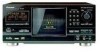
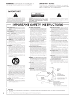
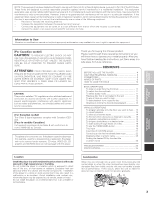
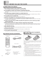
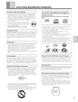
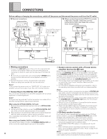
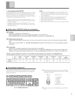
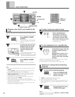
BEFORE OPERATING E Connecting another PD-F27 With these connections, the audio signals are output from one PDF27 (MASTER unit) to the other PD-F27 (SLAVE unit), and the CDs loaded in the SLAVE unit are numbered from 301 to 600, so the whole can be operated as a single 602-disc CD changer. Operation is possible from a single remote control unit. 1 Use an audio cable to connect the SLAVE LINE IN jack on the MASTER unit (first PD-F27) to the LINE OUT jack on the SLAVE unit (second PD-F27). 2 Use a control cable to connect the MASTER OUT jack on the MASTER unit (first PD-F27) to the SLAVE IN jack on the SLAVE unit (second PD-F27). Notes: • Operation of the single loader function on the SLAVE unit can not be done with the MASTER unit or the remote control unit. When operating the SLAVE unit's single loader function, please use the SLAVE unit. • When connecting 2 PD-F27 units, connect system remote control and CD•Deck synchro to the MASTER unit only. • When using 2 connected PD-F27 units, make sure that the power of both units is ON. • When not connecting a SLAVE unit, be sure to unplug the cable. Notes when 2 PD-F27 units are connected For usage • Always turn the power of both units on. • Make Optical digital out connection to both the master unit and slave unit. • Make CONTROL IN/OUT jack and CD•DECK SYNCHRO connection to the MASTER unit. For the remote control unit • SLAVE unit single loader slot operation can not be done with the remote control unit. Operate using the SLAVE unit. • The remote control's DISC (-/+), 1, ¡, 4, ¢, 7, 8, 3 buttons will function for the corresponding unit that is operating. For operation • Operation of a program spanning 2 connected units is not possible. • When 2 units are connected, disc numbers will be from 1 to 300 on the MASTER unit and from 301 to 600 on the SLAVE unit. Custom file numbers will be from 1 to 10 on the MASTER unit and from 11 to 20 on the SLAVE unit. Relay playback (Playback continues on the SLAVE unit after playback has finished on the MASTER unit) Relay playback ALL play SINGLE play CUSTOM play RANDOM play PROGRAM play BEST play PREVIOUS play HI-LITE scan ALL REPEAT BASIC OPERATIONS VARIOUS OPERATIONS Connecting a keyboard The connection terminal of this unit is designed for a U.S.-English Keyboard. Take care when using keyboards from other regions as the keys are different. Esc F1 F2 F3 F4 F5 F6 F7 F8 F9 F10 F11 F12 Print Scroll Screen Lock Pause ~! @# $ %^ ^ &( ) _+ ` 1 2 34 56 7 89 0 - = Backspace Tab QWE RT Y U I OP { [ } | ] \ Caps Lock A S D F G H J KL : ; " ' Enter Shift ZX CVB NM< > ? , . / Shift Ctrl Alt Alt Ctrl Page Inserl Home Up Delete End Page Down Num Lock / 78 Home 45 * 9 Pg Up + 6 12 End 0 Ins 3 Pg Dn Enter Del The keyboard connection jack is a six-pin mini DIN-type. When purchasing a keyboard, make sure that it accepts this type of connector. DIN-Connector 5 6 3 4 12 1 +KBD DATA 2 Reserved 3 Ground 4 +5.0 Vdc 5 +KBD CLK 6 Reserved Shield Frame Ground Power consumption of the keyboard must be 150mA or less. 7
-
 1
1 -
 2
2 -
 3
3 -
 4
4 -
 5
5 -
 6
6 -
 7
7 -
 8
8 -
 9
9 -
 10
10 -
 11
11 -
 12
12 -
13
-
14
-
15
-
16
-
17
-
18
-
19
-
20
-
21
-
22
-
23
-
24
-
25
-
26
-
27
-
28
 |
 |