Pioneer PRS-X340 Owners Manual - Page 2
Contents - specifications
 |
View all Pioneer PRS-X340 manuals
Add to My Manuals
Save this manual to your list of manuals |
Page 2 highlights
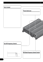
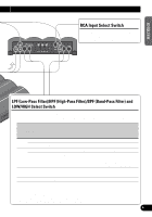
Contents Before Using This Product 2 In case of trouble 2 WARNING 2 Setting the Unit 3 Gain Control 3 Power Indicator 3 Cut Off Frequency Control 3 BFC (Beat Frequency Control) Switch 3 RCA Input Select Switch 4 LPF (Low-Pass Filter)/HPF (High-Pass- Filter)/BPF (Band-Pass Filter) and LOW/HIGH Select Switch 4 Connecting the Unit 5 Connection Diagram 6 Connecting the Power Terminal 7 Connecting the Speaker Output Terminals ...... 8 Connecting the Speakers and Input wires ........ 9 Installation 11 Example of installation on the floor mat or on the chassis 11 Fitting the end cap 12 Example of a set up with two units side by side 13 Specifications 14 1
-
 1
1 -
 2
2 -
 3
3 -
 4
4 -
 5
5 -
 6
6 -
 7
7 -
 8
8 -
9
-
10
-
11
-
12
-
13
-
14
-
15
-
16
-
17
-
18
-
19
-
20
-
21
-
22
-
23
-
24
-
25
-
26
-
27
-
28
-
29
-
30
-
31
-
32
-
33
-
34
-
35
-
36
-
37
-
38
-
39
-
40
-
41
-
42
-
43
-
44
-
45
-
46
-
47
-
48
-
49
-
50
-
51
-
52
-
53
-
54
-
55
-
56
-
57
-
58
-
59
-
60
-
61
-
62
-
63
-
64
-
65
-
66
-
67
-
68
-
69
-
70
-
71
-
72
-
73
-
74
-
75
-
76
-
77
-
78
-
79
-
80
-
81
-
82
-
83
-
84
-
85
-
86
-
87
-
88
 |
 |

1
Contents
Before Using This Product
......................
2
In case of trouble
..............................................
2
WARNING
........................................................
2
Setting the Unit
..........................................
3
Gain Control
......................................................
3
Power Indicator
................................................
3
Cut Off Frequency Control
..............................
3
BFC (Beat Frequency Control) Switch
............
3
RCA Input Select Switch
..................................
4
LPF (Low-Pass Filter)/HPF (High-Pass-
Filter)/BPF (Band-Pass Filter) and
LOW/HIGH Select Switch
........................
4
Connecting the Unit
..................................
5
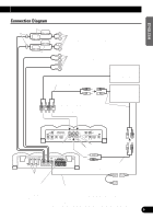
Connection Diagram
........................................
6
Connecting the Power Terminal
........................
7
Connecting the Speaker Output Terminals
......
8
Connecting the Speakers and Input wires
........
9
Installation
................................................
11
Example of installation on the floor mat
or on the chassis
......................................
11
Fitting the end cap
..........................................
12
Example of a set up with two units
side by side
..............................................
13
Specifications
..........................................
14