Poulan 1600 User Manual - Page 15
Line Replacement/Repair
 |
View all Poulan 1600 manuals
Add to My Manuals
Save this manual to your list of manuals |
Page 15 highlights
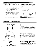
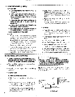
e. Makesuretheline saver is in placeand installed correctly, then insert the end of the line in the line saver as shown in Figure 18. Place spool in housing. Pressspool down. Turn and lock spool under lugs on drive gear. f. Replace the tap button; press lock tab and install the lock ring. Tum thelock ring clocicwise Pisik and fasten under all four catches on the housing. Figures 18 & 19. g. Check to be sure the lock ring is properly installed by attempting to turn the ring counterclockwise rim and pulling on it. Reinstall properly if the lock ring comes off. Figure 19. A WARNING The lock ring must be fastened under all four catches on housing. If installed incorrectly, the lock ring can fly off. h. Pull on theline to change the spool from the locked position to the operating position. Figure 20. i. Obtain correct line length by pressing tap button and pulling on the 1ine again. NOTE: Each time the tap button is pressed, approximately 2 inches of line can be pulled from the trimmer head. Figure 20. 2. Spool Replacement a. Replace the spool when the square corners of the lugs are rounded off, reduced in size, orbroken off. Figure21. b. To replace thespool, follow "Installing Spool w/Line:" 3. Line Replacement/Repair a. To replace the line on existing spool: (.)Follow "Installing Spool w/Line," steps "a-d:' and remove any line remaining on the spool. 2 -)Use a 40 foot length of WEED EATER® .080" diameter trimmer line. 3.)Insert 1/16 to 1/8 inch of the end of the line through the hole in the inner rim of the spool. Allow no more than 1/8 inch of line to extend beyond the rim to avoid interference with the drive gear. 4.)Wrapthe lineevenlyontospool in a clockwisedirection as shown by arrow on spool. Figure 22. NOTE: Wrap line firmly and evenly for proper line feed. 5.)Follow "Installing Spool w/Line:' steps b. If the line breaks off or backs up in the Trimmer Head, follow "Installing Spool w/Line; steps "a-d:' Pullslackin line until thelineistightly wound onspool, leaving4-6inches ofextended line. Continuewith steps "e-i' TURN LOCK RISC CLOCKWISE TO INSTALL fin Figure 19 -s-r. APPROXIMATELY 2 INCHES OF LINE CAN BE PULLED FROM THE TRIMMER HEAD EACH TIME THE TAP BUTTON V ---- IS PRESSED. TAP BUTTON Figure 20 0 LUG NORMAL SPOOL Figure 21 LUG WORN SPOOL WRAP LINE ON SPOOL AS SHOWN BY ARROW 1/8" Figure 22 15
-
 1
1 -
2
-
3
-
4
-
5
-
6
-
7
-
8
-
9
-
 10
10 -
 11
11 -
 12
12 -
 13
13 -
 14
14 -
 15
15 -
 16
16 -
 17
17 -
 18
18 -
 19
19 -
 20
20 -
21
-
22
-
23
-
24
 |
 |
