Poulan 1600 User Manual - Page 8
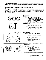
Sheeld, Awarning, Assist, Handle
 |
View all Poulan 1600 manuals
Add to My Manuals
Save this manual to your list of manuals |
Page 8 highlights
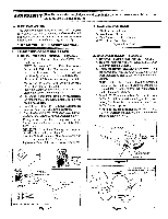
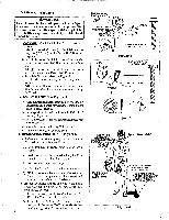
3.SHEELD r Figure 4 AWARNING Failuretoinstall theshieldin thepositionshown inFigure 4and5can result inseriousinjuryto the operator. The lengthof theshieldmust bealigned with thelengthof the driveshaft housing. Direct the widest part of theshield toward the engine. {CAUTION: The Line Limiter is sharp and can cut you. a. Match the Key (Raised area) on the Shield with the Kayway ("V" slot) on the Drive Shaft Housing. Figure 4. b. Rest the bottom of the Shield on topof theshoulder located on the Drive Shaft Housing above the Dust Cup. NOTE: The bottom of the Shield must rest on top of the shoulder of the Drive Shaft Housing. c. Install the Screws as shown in Figure 4. d. Tighten the Screws evenly and securely with a wrench. NOTE: A small space may be left between the Bracket and the Shield when hardware is fully tightened. 4.ASSIST HANDLE - Figure 5 a. Hold the Assist Handle so it is leaning back toward the Engine and aligned between the Engineand the Safety Label. Figure 5. b. Firmly push the Assist Handle over the Drive Shaft Housing. Figure 5. c. Install the Bolt in the side of the Assist Handle with the hex opening. d. Install the Washer and Wing Nut. Figure 5. e. Tighten the Wing Nut by hand only S.OPERATING POSITION Figure 6 a Before starting the Engine, stand as shown in Figure 6 and check for the following: 1). Left arm fully extended, hand holding Assist Handle. 2). Right arm slightly bent, hand holding the Rear Handle, fingers on Throttle Trigger. 3). Rear Handle below waist level. 4). Weight of tool evenly distributed between arms. 5). Without operator bending over, the Trimmer Head is near and parallel to the ground and easily contacts the material to be cut. b. Adjust the Assist Handle up or down the Drive Shaft Housing (bur above the Safety Label ) to a comfortable position. 1). Loosen the Wing Nut by hand, adjust Handle. Retighten Wing Nut by hand only. 2). Rotate the Handle from left to right if it is necessary totilt theangleoftheTrimmer Headwhen cutting a large, sloped area such as a ditch bank. 8 WIDEST PART OF SHIELD RAISED AREA BOTTOM OF SHIELD "V"SLOT SHOULDER DUST CUP KEYWAY KEY rSCREW-ofi I Na> BRACKET HARDWARE SHOWN ACTUAL SIZE Figure 4 HARDWARE SHOWN ACTUAL SIZE WING WASHER SAFETY LABELS 1:1 1 Figure 5 RIGHT ARM SLIGHTLY BENT. HAND HOLDING REAR f HANDLE, FINGERS ON THROTTLE vTRIGG ER / SAFETY FACE SHIELD ,o0 REAR HANDLE IS BELOW WAIST LEVEL LEFT ARM EXTENDED, HAND HOLDING ASSIST HANDLE TRIMMER HEAD IS NEAR THE GROUND AND EASILY CONTACTS MATERIAL TO BE CUT Figure 6
-
 1
1 -
2
-
 3
3 -
 4
4 -
 5
5 -
 6
6 -
 7
7 -
 8
8 -
 9
9 -
 10
10 -
 11
11 -
 12
12 -
 13
13 -
14
-
15
-
16
-
17
-
18
-
19
-
20
-
21
-
22
-
23
-
24
 |
 |
