Poulan 1980-02 User Manual - Page 4
Adjusting, Screw
 |
View all Poulan 1980-02 manuals
Add to My Manuals
Save this manual to your list of manuals |
Page 4 highlights
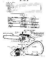
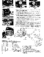
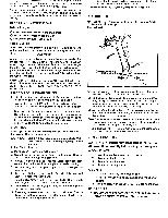
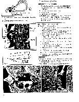
Figure 1 r4kgrkareq.... - • 77-rfS.V. .otkAL Figure 4 1"1. V I) Figure 5 Adjusting Screw Ora Figure 2 r4"5•WFigure 3 1. Remove the bar mounting nuts, washers, bar clamp and outer guide bar plate. (Note position of the plate.)Figure 1 2. Mount the slotted end of the bar over the bar mounting studs and slide bar rearward as far as possible. Figure 2 3. Place the chain over the sprocket and engage the drive link tangs between sprocket teeth. Figure 3 4. Starting at the top of the bar, gradually work the chain into the groove of the bar until all the drive links are engaged in the bar groove. Make sure the cutting edges of the chain face forward as shown in Figure 5. 5. Turn (counter-clockwise) the bar adjusting screw (see chain adjustment photo Figure 6) until adjusting pin in Figure 4 is in extreme rear position. Pull bar forward until adjusting pin seats in the hole of the bar. 6. Replace outer guide bar plate. (Note position). Replace bar clamp, washers and nuts on the bar mounting studs and tighten nuts finger tight. Figure 5 CHAIN ADJUSTMENT (Figure 6) Raise tip of bar and turn the bar adjusting screw (clockwise) until the bottom of all tie straps and cutters of the chain make contact with the bottom rails of the guide bar. There should be no droop or slack in the chain. Chain should move around guide bar freely, when pulled by hand. Continue to hold the tip of the bar and tighten the bar mounting nuts securely, with the bar wrench. Run engine slowly for a minute or two while keeping the chain well oiled. Stop engine and check chain tension and readjust if necessary. Check chain tension (continued on Page 5) BOW INSTALLATION Figure 6 •f• 1 O O a aB • • a a ° 0_ • Ref. No. Part No. 1 2 3 4 • 5 6 4484 51654 11176 22087 23447 1615 Qty. 1 1 1 2 . 2 3 7 1207 1 8 1208 1 9 625567 2 Description 13" Bow Guide Chain Cover - Bow Guide Nut - Bow Mounting Spacer - Bow Mounting Nut - Adapter & Bumper Mounting (14/ -20 flexloc) Bumper - (left) Bumper - (right) Screw - Bumper Mounting (1/4-20 x I% hex head) 4 4.® BOW ASSEMBLY INSTRUCT: 1. Install two 23447 spacers o• slot on top and to the right. 2. Attach 1207 and 1208 bumpers 625567 screws and two 1615 locknuts. 3. Mount bow guide, chain and 11176 cover on saw while making sure that adjusting pin enters hole in bow guide. 4. Install 22087 nuts finger tight, adjust chain tension and tighten nuts.
-
 1
1 -
 2
2 -
 3
3 -
 4
4 -
 5
5 -
 6
6 -
 7
7 -
 8
8 -
 9
9
 |
 |
