Poulan PP11530ES User Manual
Poulan PP11530ES Manual
 |
View all Poulan PP11530ES manuals
Add to My Manuals
Save this manual to your list of manuals |
Poulan PP11530ES manual content summary:
- Poulan PP11530ES | User Manual - Page 1
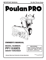
IMPORTANT MANUAL Do Not Throw Away OWNER'S MANUAL MODEL NUMBER: PP11530ES SNOW THROWER WARNING: Read the Owner's Manual and follow all Warnings and Safety Instructions. Failure to do so can result in serious injury. Always Wear Eye Protection During Operation 420915 07.15.08 TH Printed in - Poulan PP11530ES | User Manual - Page 2
Engine exhaust, some of its constituents, and certain vehicle components contain or emit chemicals known to the State of California to cause cancer and birth defects or other reproductive harm. Training 1. Read, understand and follow all instructions on the machine and in the manual rotating parts. - Poulan PP11530ES | User Manual - Page 3
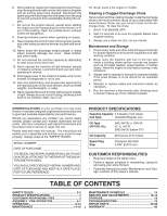
the instructions under "Maintenance" and "Storage" sections of this owner's manual. TABLE OF CONTENTS SAFETY RULES 2-3 MAINTENANCE SCHEDULE 14 PRODUCT SPECIFICATIONS 3 SERVICE AND ADJUSTMENTS 16-18 CUSTOMER RESPONSIBILITIES 3 STORAGE 18 ASSEMBLY / PRE-OPERATION 5-7 TROUBLESHOOTING - Poulan PP11530ES | User Manual - Page 4
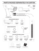
PARTS PACKED SEPARATELY IN CARTON (1) MULTIWRENCH (180684) (1) POWER CORD (198563) (1) SAFTEY IGNITION KEY (35062) (1) AUGER CONTROL ROD (1) TRACTION DRIVE CONTROL ROD (1) DISCHARGE CHUTE EXTRA SHEAR BOLTS - Poulan PP11530ES | User Manual - Page 5
these instructions and this manual in its entirety before you attempt to assemble or operate your new snow thrower. Reading the entire manual will familiarize cover. Store the extra shear bolts, nuts and multi-wrench provided in parts bag in the toolbox. NOTE: The multi-wrench may be used for - Poulan PP11530ES | User Manual - Page 6
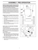
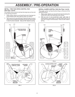
ASSEMBLY / PRE-OPERATION INSTALL TRACTION DRIVE CONTROL ROD (See Figs. 3 and 4) The traction drive control rod has the long loop on the end of the spring as shown. 1. Slide rubber sleeve up rod and hook end of spring into pivot bracket with loop opening down as shown. 2. With top end of rod - Poulan PP11530ES | User Manual - Page 7
ASSEMBLY / PRE-OPERATION INSTALL DISCHARGE CHUTE / CHUTE ROTATOR HEAD (See Fig. 7) NOTE: The multi-wrench provided in your parts bag may be used to install the chute rotator head. 1. Place discharge chute assembly on top of chute base with discharge opening toward front of - Poulan PP11530ES | User Manual - Page 8
yourself with the location of various controls and adjustments. Save this manual for future reference. These symbols may appear on your snow READ AND FOLLOW ALL SAFETY INFORMATION AND INSTRUCTIONS BEFORE USE OF THIS PRODUCT. KEEP THESE INSTRUCTIONS FOR FUTURE REFERENCE. IGNITION KEY. INSERT - Poulan PP11530ES | User Manual - Page 9
CLEAN-OUT TOOL LH TURN TRIGGER LIGHT HANDLE KNOB NOTE: ITEMS ABOVE ARE SHOWN IN THEIR TYPICAL LOCATION ON THE ENGINE. ACTUAL LOCATION MAY VARY WITH THE ENGINE ON YOUR UNIT. MUFFLER TOOLBOX DRIFT CUTTER SKID PLATE AUGERS FIG. 10 MEETS A.N.S.I. SAFETY REQUIREMENTS Our snow throwers conform to - Poulan PP11530ES | User Manual - Page 10
clear of all persons, small children and pets at all times including startup. If the discharge chute or auger become clogged, shut-off engine and wait for all moving parts to stop. Use the clean-out tool, NOT YOUR HANDS, to unclog the chute and/or auger. The DIRECTION in which snow - Poulan PP11530ES | User Manual - Page 11
prevent accidental starting. • Release the auger control lever and shut off the engine. • Remove the clean-out tool from it's mounting clip. Grasp FORWARD AND BACKWARD (See Fig. 17) NOTE: The wrench provided in your parts bag may be used SELF-PROPELLING, forward and reverse movement of to adjust - Poulan PP11530ES | User Manual - Page 12
, providing additional service before requiring replacement engine problems, the fuel system should be emptied before storage of 30 days or longer. Drain the gas tank, start the engine and let it run until the fuel lines and carburetor are empty. Use fresh fuel next season. See Storage Instructions - Poulan PP11530ES | User Manual - Page 13
START - ELECTRIC STARTER 1. Insert safety ignition key (packed separately in parts bag) into ignition slot until it clicks. DO NOT turn the key section of this manual. • For extremely heavy snow, reduce the width of snow removal by overlapping previous path and moving slowly. • Keep engine clean and - Poulan PP11530ES | User Manual - Page 14
your engine run better and last longer. • Follow the maintenance schedule in this manual. NOTE: Use only Original Equipment Manufacturer (OEM) parts to service this your local (OEM) belts available from your nearest dealer. Using other parts dealer. Tire sealant also prevents tire dry rot and - Poulan PP11530ES | User Manual - Page 15
tilted, resting on the frame with the left wheel removed, will help drain any oil trapped inside the engine. (See "TO REMOVE WHEELS" in the Service and Adjustments section of this manual). 1. Remove safety ignition key and disconnect spark plug wire from spark plug. Place wire where it cannot come - Poulan PP11530ES | User Manual - Page 16
service or adjustments: 1. Be sure throttle is in STOP position. 2. Remove safety ignition key. 3. Make sure the augers and all moving parts is discharged, see "TO CONTROL SNOW DISCHARGE" in the Operation section of this manual. SHEAR BOLTS (See Fig. 22) AUGER SHEAR BOLTS Both right and left-hand - Poulan PP11530ES | User Manual - Page 17
be replaced by a qualified service center. NOTE: It is recommended section of this manual. 4. REMOVE ENGINE PULLEY - Remove bolt, lockwasher and flat washer securing pulley to engine crankshaft. Remove local parts belt around pulleys and inside belt keepers. 17 dealer. Tire sealant also prevents tire - Poulan PP11530ES | User Manual - Page 18
does not operate properly due to suspected carburetor problems, take your snow thrower to a qualified service center. ENGINE SPEED Never tamper with the engine governor, which is factory set for proper engine speed. Overspeeding the engine above the factory high speed setting can be dangerous and - Poulan PP11530ES | User Manual - Page 19
TROUBLESHOOTING See appropriate section in manual unless directed to a qualified service centre. PROBLEM CAUSE CORRECTION Does not start 1. Fuel shut-off valve (if so equipped) in OFF position. 2. Safety ignition key is not inserted. 3. Out of fuel. 4. Throttle - Poulan PP11530ES | User Manual - Page 20
REPAIR PARTS SNOW THROWER - MODEL PP11530ES (96192001902) AUGER HOUSING / IMPELLER ASSEMBLY 5 11 6 15 14 13 4 12 16 11 12 3 11 1 9 10 2 11 7 8 17 33 32 34 30 31 31 29 26 28 27 35 18 25 24 23 22 21 19 01.07.004-B 36 20 21 22 23 2 (EXPLODED) 20 - Poulan PP11530ES | User Manual - Page 21
REPAIR PARTS SNOW THROWER - MODEL PP11530ES (96192001902) AUGER HOUSING / IMPELLER ASSEMBLY KEY NO. 1 2 3 4 5 6 7 8 9 10 11 12 13 14 15 16 17 18 19 20 21 22 23 24 25 26 27 28 29 30 31 32 33 34 35 36 PART NO. 175321X479 196710 188909 191079 175322 178675X008 192199 405400 73800400 74780426 155377 - Poulan PP11530ES | User Manual - Page 22
REPAIR PARTS SNOW THROWER - MODEL PP11530ES (96192001902) AUGER HOUSING / IMPELLER ASSEMBLY 1 3 (5x) 4 (5x) 2 01.07.003-A KEY NO. 1 2 3 4 PART NO. 404930X428 404933X479 72270505 155377 DESCRIPTION AUGER HOUSING SCRAPPER BAR CARRIAGE BOLT 5/16−18 X .625 NUT 5/16−18 2 1 KEY NO. 1 2 PART NO. - Poulan PP11530ES | User Manual - Page 23
SNOW THROWER - MODEL PP11530ES (96192001902) AUGER HOUSING / IMPELLER ASSEMBLY 2 3 1 1 2 3 01.07.024-B KEY NO. 1 2 3 PART NO. 420478 411939 179582 DESCRIPTION AUGER BEARING BEARING PLUG SCREW 5/16−18 X 1.00 3 4 3 01.11.001-A 1 4 2 KEY NO. 1 2 3 4 PART NO. 174762X479 178777X479 - Poulan PP11530ES | User Manual - Page 24
SNOW THROWER - MODEL PP11530ES (96192001902) AUGER HOUSING / IMPELLER ASSEMBLY 1 3 2 KEY PART 4 NO. NO. DESCRIPTION 1 181160X479 DRIFT CUTTER BAR 2 72270506 CARRIAGE BOLT 5/16−18 X .750 5 3 3 179246 PLASTIC WASHER 1 4 3 5 4 4 10040500 LOCKWASHER 5/16 5 128638 NUT 5/16 - Poulan PP11530ES | User Manual - Page 25
PP11530ES (96192001902) CONTROL PANEL / DISCHARGE CHUTE 5 7 14 3 15 *13 KEY NO. 1 2 3 4 5 6 7 *8 *9 *10 *11 *12 *13 14 15 PART CARRIAGE BOLT 5/16−18 X .50 NUT 5/16−18 DEFLECTOR SPRING (SERVICE PART) DEFLECTOR CONTROL HEAD (SERVICE PART) DEFLECTOR CONTROL CABLE *10 *9 *8 6 *12 *11 01.09. - Poulan PP11530ES | User Manual - Page 26
THROWER - MODEL PP11530ES (96192001902) CONTROL PANEL / DISCHARGE CHUTE 2 2 *3 1 *6 KEY NO. 1 2 *3 *4 *5 *6 PART NO. 420337 *5 NOTES: 1. ITEMS INDICATED WITH AN * ARE LISTED AS REFERENCE FOR SERVICE PARTS ONLY. 2 1 KEY PART NO. NO. DESCRIPTION 1 188303 STEER CABLE 2 74041024 - Poulan PP11530ES | User Manual - Page 27
HANDLES 3 SNOW THROWER - MODEL PP11530ES (96192001902) 10 2 11 9 5 7 6 8 47 9 1 13 8 13 14 12 12 14 01.08.002-D KEY NO. 1 2 3 4 5 6 7 8 9 10 11 12 13 14 PART NO. 412683X479 412681X479 412682X479 412679X008 420889X008 412677 412680 169675 17060408 414280 414281 178899 19131316 72120618 - Poulan PP11530ES | User Manual - Page 28
SCREW 5/16−18 X 1.50 SCREW 5/16−18 X 1.75 NUT 5/16−18 01.08.004-A 1 4 3 2 4 KEY NO. 1 2 3 4 PART NO. 419797X479 405784X479 17490508 17000616 DESCRIPTION LOWER HANDLE PIVOT SUPPORT WELDMENT SCREW 5/16−18 X .50 SCREW 3/8−16 X 1.00 3 4 4 01.05.002-A NOTE: All component dimensions given in - Poulan PP11530ES | User Manual - Page 29
SNOW THROWER - MODEL PP11530ES (96192001902) 2 1 3 8 9 KEY NO. 1 2 3 4 5 6 7 8 9 10 PART NO. 180480 405740 1 inch = 25.4 mm IMPORTANT: Use only Original Equipment Manufacturer (O.E.M.) replacement parts. Failure to do so could be hazardous, damage your snow thrower and void your warranty. 29 - Poulan PP11530ES | User Manual - Page 30
SNOW THROWER - MODEL PP11530ES (96192001902) 4 5 2 1 KEY PART NO. NO. DESCRIPTION 31 412675X004 INTERLOCK SPRING 2 414572 INTERLOCK CAM 3 178831 TORSION SPRING 4 169675 RETAINER 5 17060410 SCREW 1/4−20 X .625 6 421252X004 INTERLOCK STOP 6 01.08.007-B 3 7 2 5 6 4 5 1 4 - Poulan PP11530ES | User Manual - Page 31
DRIVE SNOW THROWER - MODEL PP11530ES (96192001902) 8 1b 7 7 1b 1a 6 4 3 5 6 2 3 4 01.03.002-A KEY NO. 1 1a 1b 2 3 4 5 6 7 8 PART NO. 404923 404307 9465M1 402691 174697 179830 146315 17490508 155443 189282 DESCRIPTION AXLE ASSEMBLY (assy of 1a,1b) AXLE SHAFT ROLL PIN 3/16 X 1.50 SPROCKET - Poulan PP11530ES | User Manual - Page 32
REPAIR PARTS DRIVE SNOW THROWER - MODEL PP11530ES (96192001902) 2 ITEM 43 EXPLODED 69 1 16 68 17 71 74 15 14 15 12 9 11 11 20 9 4 9 10 11 13 4 8 7 4 21 6 5 4 23 18 22 19 - Poulan PP11530ES | User Manual - Page 33
PP11530ES (96192001902) KEY NO. 1 2 3 4 5 6 7 8 9 10 11 12 13 14 15 16 17 18 19 20 21 22 23 24 25 26 27 28 29 30 31 32 33 34 35 36 37 38 PART 5/16−18 X 1.00 SPACER TRACTION PULLEY WASHER 3/8 LOCKWASHER 3/8 LOCKWASHER BELT GUIDE IDLER ARM IDLER BRACKET IDLER PULLEY SCREW 5/16−18 X 1.50 NUT 5/16 - Poulan PP11530ES | User Manual - Page 34
PARTS SNOW THROWER - MODEL PP11530ES (96192001902) CHASSIS / ENGINE / PULLEYS 4 2 4 3 1 1 3 01.00.008-A KEY NO. - - 1 2 3 4 PART NO 409346X428 417014X428 150406 150078 DESCRIPTION TECUMSEH ENGINE MODEL LH358SA-159642A FRAME ENGINE MOUNT PLATE BOLT 3/8−16 SCREW 5/16−18 X .750 KEY PART - Poulan PP11530ES | User Manual - Page 35
REPAIR PARTS WHEELS SNOW THROWER - MODEL PP11530ES (96192001902) 2 2 17 23 43 5 6 7 8 9 10 11 12 13 14 15 16 17 18 19 20 21 22 23 24 PART NO. 405161 184471 12000045 192126 182466 187622 194941 179139 189282 194940 174697 193506X479 179148X479 17490508 194943X008 194944X008 181847 17600406 - Poulan PP11530ES | User Manual - Page 36
WHEELS SNOW THROWER - MODEL PP11530ES (96192001902) 1 2 01.06.006-A KEY NO. 1 2 PART NO. 196752X421 196753X421 DESCRIPTION WHEEL ASSEMBLY LH WHEEL ASSEMBLY RH 1 2 01.15.003-A KEY PART NO. NO. DESCRIPTION 3 1 410293 CABLE BRACKET LH 2 410294 CABLE BRACKET RH 3 17060410 SCREW 1/4−20 - Poulan PP11530ES | User Manual - Page 37
REPAIR PARTS BAG OF PARTS SNOW THROWER - MODEL PP11530ES (96192001902) 3 2 4 5 8 1 7 6 9 KEY NO. 1 2 3 4 11 10 5 6 7 8 9 10 11 12 14 13 13 14 12 01.14.003-A PART NO. 198563 169675 180684 184505 179829 179246 191730 72250505 751153 73800600 19131316 198636 198638 73800400 - Poulan PP11530ES | User Manual - Page 38
DESCRIPTION DECAL, DANGER DECAL, POULAN PRO, 11 HP / 30" DECAL, DANGER, DEFLECTOR DECAL, DANGER DECAL, POULAN PRO DECAL, INSTRUCTION DECAL, LH TRIGGER DECAL, RH TRIGGER DECAL, SPEED CONTROL DECAL, REMOTE DEFLECTOR CONTROL OWNER'S MANUAL, ENGLISH OWNER'S MANUAL, FRENCH NOTE: All component dimensions - Poulan PP11530ES | User Manual - Page 39
SERVICE NOTES 39 - Poulan PP11530ES | User Manual - Page 40
does not apply to the engine or components parts thereof. Please refer to the and maintained in accordance with the instructions furnished. This Warranty does not apply service dealer. Should you have any unanswered questions concerning this Warranty, please contact: Poulan Pro Customer Service
-
 1
1 -
 2
2 -
 3
3 -
 4
4 -
 5
5 -
 6
6 -
 7
7 -
8
-
9
-
10
-
11
-
12
-
13
-
14
-
15
-
16
-
17
-
18
-
19
-
20
-
21
-
22
-
23
-
24
-
25
-
26
-
27
-
28
-
29
-
30
-
31
-
32
-
33
-
34
-
35
-
36
-
37
-
38
-
39
-
40
 |
 |
OWNER'S MANUAL
MODEL NUMBER:
PP11530ES
SNOW THROWER
Always Wear Eye Protection During Operation
IMPORTANT MANUAL
Do Not Throw Away
WARNING:
Read the Owner's Manual and
follow all Warnings and Safety
Instructions.
Failure to do so
can result in serious injury.
420915
07.15.08
TH
Printed in U.S.A.