Poulan PP11530ES User Manual - Page 6
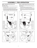
Install Traction Drive Control Rod, See Figs. 3 And 4, Install Auger Control Rod See Figs. 5 And 6
 |
View all Poulan PP11530ES manuals
Add to My Manuals
Save this manual to your list of manuals |
Page 6 highlights
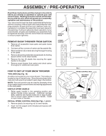
ASSEMBLY / PRE-OPERATION INSTALL TRACTION DRIVE CONTROL ROD (See Figs. 3 and 4) The traction drive control rod has the long loop on the end of the spring as shown. 1. Slide rubber sleeve up rod and hook end of spring into pivot bracket with loop opening down as shown. 2. With top end of rod positioned under left side of control panel, push rod down and insert top end of rod into hole in drive control bracket. Secure with retainer spring. INSTALL AUGER CONTROL ROD (See Figs. 5 and 6) The auger control rod has the short loop on the end of the spring as shown. 1. Slide rubber sleeve up rod and hook end of spring into control arm with loop opening up as shown. 2. With top end of rod positioned under right side of control panel, push down on rod and insert end of rod into hole in auger control bracket. Secure with retainer spring. TRACTION DRIVE CONTROL ROD RUBBER SLEEVE LOOP OPENING DOWN PIVOT BRACKET FIG. 3 TRACTION DRIVE CONTROL LEVER RETAINER SPRING DRIVE CONTROL BRACKET FIG. 4 TRACTION DRIVE CONTROL ROD CONTROL ARM AUGER CONTROL ROD RUBBER SLEEVE LOOP OPENING UP FIG. 5 AUGER CONTROL ROD AUGER CONTROL RETAINER LEVER SPRING AUGER CONTROL BRACKET FIG. 6 6
-
 1
1 -
 2
2 -
 3
3 -
 4
4 -
 5
5 -
 6
6 -
 7
7 -
 8
8 -
 9
9 -
 10
10 -
 11
11 -
 12
12 -
13
-
14
-
15
-
16
-
17
-
18
-
19
-
20
-
21
-
22
-
23
-
24
-
25
-
26
-
27
-
28
-
29
-
30
-
31
-
32
-
33
-
34
-
35
-
36
-
37
-
38
-
39
-
40
 |
 |
