ProForm 160 Elliptical English Manual - Page 8
Position an Inner Handlebar Cover 18 and an
 |
View all ProForm 160 Elliptical manuals
Add to My Manuals
Save this manual to your list of manuals |
Page 8 highlights
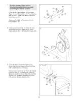
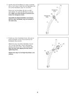
6. Identify the Left Handlebar (8), which is marked 6 with a "Left" sticker. Insert the Left Handlebar into one of the Handlebar Legs (11) as shown. Attach the Left Handlebar (8) with two M8 x 42mm Bolts (71) and two M8 Nylon Locknuts (96). Make sure that the Nylon Locknuts are inside the hexagonal holes. Assemble the Right Handlebar (not shown) and the other Handlebar Leg (not shown) in the same way. 8 Hexagonal Hole 96 Hexagonal Hole 11 71 7. Position an Inner Handlebar Cover (18) and an Outer Handlebar Cover (19) around the Left 7 Handlebar (8) as shown. Attach the Inner and Outer Handlebar Covers (18, 19) with three M4 x 16mm Self-tapping Screws (79) and an M4 x 13mm Washer (93). Start all three Self-tapping Screws before tightening them. 19 Repeat this step for the Right Handlebar (not shown). 18 79 8 79 93 8
-
 1
1 -
2
-
 3
3 -
 4
4 -
 5
5 -
 6
6 -
 7
7 -
 8
8 -
 9
9 -
 10
10 -
 11
11 -
 12
12 -
 13
13 -
14
-
15
-
16
-
17
-
18
-
19
-
20
-
21
-
22
-
23
-
24
-
25
-
26
-
27
-
28
 |
 |
