ProForm 2500 English Manual - Page 7
Tighten the Screws into the Left Top Handgrip.
 |
View all ProForm 2500 manuals
Add to My Manuals
Save this manual to your list of manuals |
Page 7 highlights
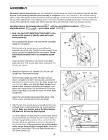
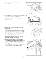
4. Loosely thread a 1/2" Tek Screw (116) into the left side of the Crossbar (46). 4 116 46 (Leave loose) 5. Tighten tighten a 3/4" Tek Screw (35) into the right side of the Crossbar (46) and the Right Upright (55). 5 Attach the Console Base (38) to the Uprights (55, 64) with four 1/2" Screws (33). Make sure that the Wire Harness (49) is not pinched. 49 33 38 35 46 55 33 64 6. Tighten the 1/2" Tek Screw (116) in the left side of the Crossbar (46). 6 Orient one of the Handgrip Extensions (34) as shown and insert it as far as possible into the post on the left Upright (64). If necessary, tap the Handgrip Extension with a rubber mallet to fully insert it. Attach the Handgrip Extension with two 3/4" Tek Screws (35), one towards the front of the post, and the other towards the back. Attach the other Handgrip Extension to the post on the right Upright (not shown) in the same way. 116 46 35 Post 34 64 35 7. See the inset drawing. Identify the Left Top Handgrip (31); there are identifying marks inside the Handgrips. Set the Left Top Handgrip on the left Handgrip Extension (34). Insert two 1/2" Screws (33) into the two holes in the Handgrip Extension indicated by the arrows. Tighten the Screws into the Left Top Handgrip. Important: Do not tighten the Screws into the plastic bosses on the bottom of the Left Top Handgrip. 7 31 Bosses 33 31 34 43 64 7
-
 1
1 -
 2
2 -
 3
3 -
 4
4 -
 5
5 -
 6
6 -
 7
7 -
 8
8 -
 9
9 -
 10
10 -
 11
11 -
 12
12 -
13
-
14
-
15
-
16
-
17
-
18
-
19
-
20
-
21
-
22
-
23
-
24
-
25
-
26
-
27
-
28
-
29
-
30
-
31
 |
 |
