ProForm 2500 English Manual - Page 8
Insert the Left and Right Cup Holders 39, 59 into - treadmill parts
 |
View all ProForm 2500 manuals
Add to My Manuals
Save this manual to your list of manuals |
Page 8 highlights
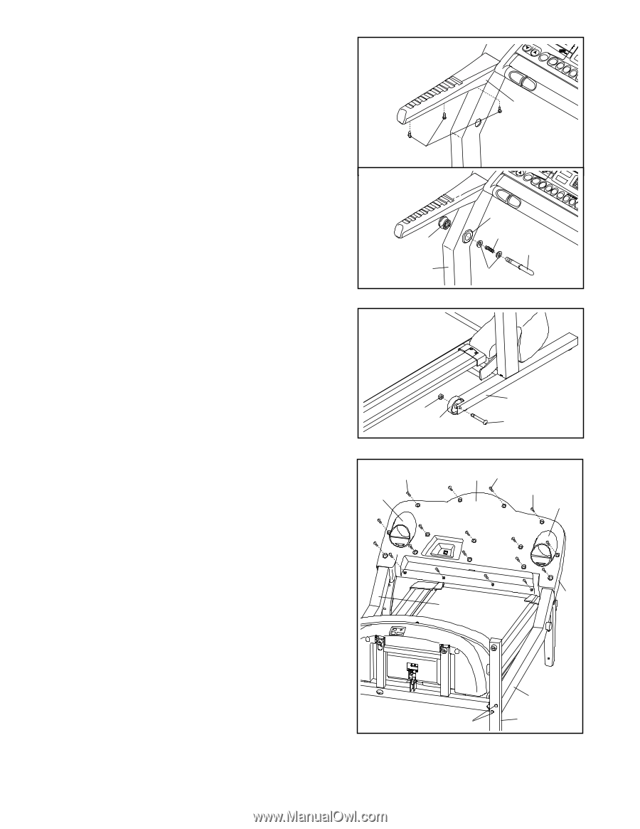
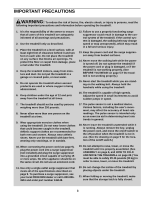
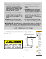
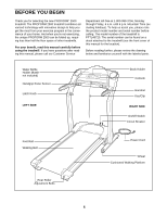
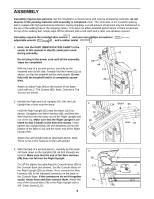
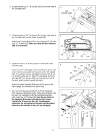
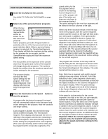
8. Refer to drawing 8a. Attach the matching Left Bottom Handgrip (82) with three 1/2" Screws (33). 8a Attach the Right Top Handgrip and the Right Bottom Handgrip (not shown) as described above. 82 Refer to drawing 8b. Press the Lock Knob Sleeve (104) 33 into the Left Upright (64). If necessary, use a rubber mal- let to tap the Lock Knob Sleeve into the Upright. 8b Remove the Lock Knob (32) from the Lock Pin (111). Make sure that the Lock Pin Collars (100) and the Spring (105) are on the Lock Pin as shown. Insert the Lock Pin into the Lock Knob Sleeve (104) and the Left Upright (64), 32 and tighten the Lock Knob onto the Lock Pin. 64 104 105 111 100 9. Attach a Wheel (58) to the right side of the Base (114) with a Wheel Bolt (56) and a Nut (3) as shown. 9 Attach a Wheel to the left side of the Base (not shown) in the same way. 3 58 114 56 10. Carefully lower the Uprights (55, 64) as shown. Press the Console Back (40) onto the back of the Console Base (38). Make sure that Console Back and the Console Base are mated correctly and that no wires are pinched. Tighten two 1/2" Silver Screws (115) into the indicated holes. Tighten 3/4" Screws (37) into the remaining holes in the Console Back. Make sure that the side of the Left Upright (64) is flush with the left side of the Base (114). Firmly tighten, but do not overtighten, the two Upright Bolts (13) in the left side of the Base. Then, tighten the two Upright Bolts (not shown) in the other side of the Base. Make sure that the Right Upright (55) is flush with the right side of the Base (114). Raise the Uprights (55, 64) back to the vertical position. Insert the Left and Right Cup Holders (39, 59) into the large holes in the Console Base (38). There may be extra hardware after assembly is completed. 10 115 39 40 37 115 59 38 55 64 13 114 11.Make sure that all parts are properly tightened before you use the treadmill. Keep the included allen wrench in a secure place; the allen wrench is used to adjust the walking belt (see page 25). To protect the floor or carpet from damage, place a mat under the treadmill. 8
-
 1
1 -
2
-
 3
3 -
 4
4 -
 5
5 -
 6
6 -
 7
7 -
 8
8 -
 9
9 -
 10
10 -
 11
11 -
 12
12 -
 13
13 -
14
-
15
-
16
-
17
-
18
-
19
-
20
-
21
-
22
-
23
-
24
-
25
-
26
-
27
-
28
-
29
-
30
-
31
 |
 |