ProForm 380 User Manual - Page 7
Cover 44. Attach the Wire Cover to the Console Base - e treadmill
 |
View all ProForm 380 manuals
Add to My Manuals
Save this manual to your list of manuals |
Page 7 highlights
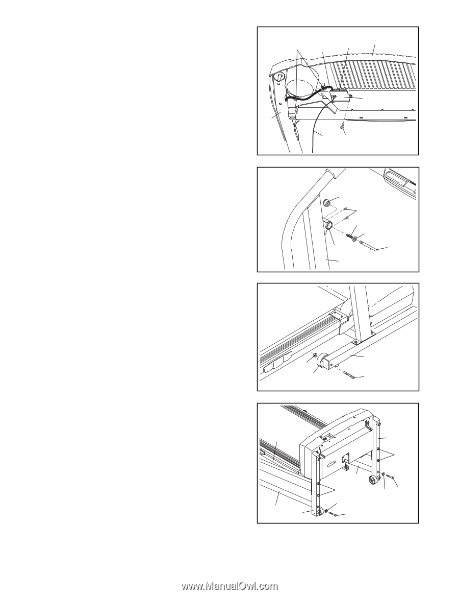
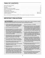
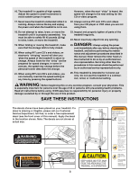
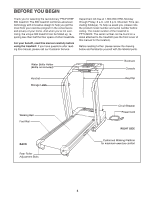
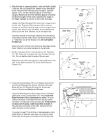
6. Insert the excess Wire Harness (42) into the large hole in the side of the Right Handrail (72). Securely tighten the plastic ties on the bottom of the Console Base (47) to prevent the Wire Harness from slipping. Then, cut off the ends of the plastic ties. Route the Wire Harness (42) through the indicated opening in the Console Base (47). If you connected the Audio Cable (56) in step 5, route it through the slot in the Wire Cover (44). Attach the Wire Cover to the Console Base with a 1/2" Silver Screw (49). 6 Ties 42 Opening 47 44 72 56 49 7. Attach the Storage Latch (36) to the Left Upright (73) with two 3/4" Screws (2). Remove the Lock Knob (30) 7 from the Lock Pin (35). Make sure that the Lock Pin Collar (33) and the Spring (32) are on the Lock Pin as shown. Insert the Lock Pin into the Storage Latch and tighten the Lock Knob back onto the Lock Pin. 8. Attach a Wheel (66) to the inner side of the Base (69) with a Wheel Bolt (64) and a Nut (13) as shown. Do not 8 overtighten the Wheel Bolt. The Wheel should be able to spin freely. Attach a Wheel (66) to the other side of the Base (69) in the same way. 30 2 32 33 36 35 73 69 13 66 64 9. Lower the Handrails (71, 72) to the floor. Align the Right Handrail (72) with the indicated hole in the Base (69). Finger tighten a 3 1/2" Bolt (61) with a 5/16" Washer (48) into the Base and the Right Handrail. Attach the Left Handrail (71) in the same way. Make sure that the Frame (86) is centered between the Handrails. Firmly tighten the 3 1/2" Bolts (61) and the Upright Nuts (109). Refer to step 3. Firmly tighten the 1" Bolts (63). Then, raise the Handrails. 9 86 72 69 71 109 48 61 69 109 48 61 10.Make sure that all parts are properly tightened before you use the treadmill. Note: Extra hardware may be included. Keep the included allen wrenches in a secure place. The large allen wrench is used to adjust the walking belt (see page 21). To protect the floor or carpet, place a mat under the treadmill. 7
-
 1
1 -
 2
2 -
 3
3 -
 4
4 -
 5
5 -
 6
6 -
 7
7 -
 8
8 -
 9
9 -
 10
10 -
 11
11 -
 12
12 -
13
-
14
-
15
-
16
-
17
-
18
-
19
-
20
-
21
-
22
-
23
-
24
-
25
-
26
-
27
 |
 |