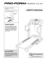
ProForm 485 Cx Treadmill User Manual - Page 6
Assembly
 |
View all ProForm 485 Cx Treadmill manuals
Add to My Manuals
Save this manual to your list of manuals |
Page 6 highlights
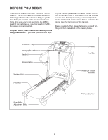
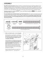
ASSEMHBandLraYil Bolt (20)-4 Assembly requires two persons. Set the treadmill in a cleared area and remove all packing materials; do not dispose of the packing materials until assembly is completed. Note: The underside of the walking belt is coated with high-performance lubricant. During shipping, a small amount of lubricant may be transferred to the top of the walkinSgcbreewlt o(3r )t-h1e5shipping carton. This is a normal condition and does not affect treadmill performance. If there is lubricant on top of the walking belt, wipe off the lubricant with a soft cloth and a mild, non-abrasive cleaner. Latch Screw Assembly requires the included hex keys, your(XoXwXn)-P2hillips screwdriver , and your own rubber mallet . 3/4" Tek Screw (58)-8 For help identifying the assembly hardware, see the drawings below. The number in parentheses below each drawing is the key number of the part, from the PART LIST near thSecernedwo(f3t)h-i2s manual. The number following the parentheses is the quantity needed for assembly. Note: If a part is not in the parts bag, check to see if it has been pre-assembled. To avoid damaging plastic parts, do not use power tools for assembly. Extra hard- ware may be included. #8 x 3/4" Screw 1" Tek Screw (19)-14 (22)-4 1/2" Screw (33)-1 Handrail Bolt/Extension Leg Bolt (64)-8 1/4 Star Washer (8)-10 Long Handrail Bolt (106)-2 H W 1. Make sure that the power cord is unplugged. 1 With the help of a second person, carefully tip the treadmill onto its left side as shown. Partially fold the Frame (58) so the treadmill is more sta- 84 82 82 77 ble. Do not fully fold the treadmill until it is completely assembled. 89 22 Insert an Extension Leg (89) into the base of the Uprights (84) as shown. Note: Be careful not to pinch the Upright Wire Harness (77) in the base of the Upright. To fully insert the Ex3t/e4n"sTieokn SLecrge,wit may be necessary to tap on it with a m(2a)-ll4et. Next, insert two Extension Leg Bolts (64) with two Star Washers (8) into the bottom of the Extension Leg, and firmly tighten the Extension Leg Bolts. 8 64 58 Attach two Base Pads (82) to th5e" bBaoslte(1o0f 6th)-e2 Uprights (84) with two 1" Tek Screws (22). 6
-
 1
1 -
 2
2 -
 3
3 -
 4
4 -
 5
5 -
 6
6 -
 7
7 -
 8
8 -
 9
9 -
 10
10 -
 11
11 -
 12
12 -
13
-
14
-
15
-
16
-
17
-
18
-
19
-
20
-
21
-
22
-
23
-
24
-
25
-
26
-
27
-
28
-
29
-
30
-
31
-
32
-
33
-
34
-
35
-
36
 |
 |
