ProForm 485 E English Manual - Page 8
Slide a Weld Spacer 49 and a Pivot Bushing 56
 |
View all ProForm 485 E manuals
Add to My Manuals
Save this manual to your list of manuals |
Page 8 highlights
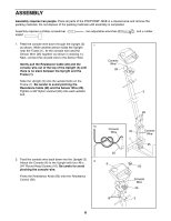
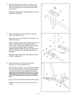
6. Refer to drawing 6a. Push the left Pedal Arm (12) until the left Crank Arm (59) is at the back of the Side Shields (4, 5) as shown. Apply the included grease to the axles in the locations indicated. Slide a Weld Spacer (49) and a Pivot Bushing (56) onto the left axle on the Upright (3). Make sure that the open side of the Weld Spacer is facing the Upright and that the Pivot Bushing is turned as shown. Slide the left Handlebar (8) onto the left axle on the Upright (3). Make sure that the Handlebar slides onto the Pivot Bushing (56) on the axle. Slide another Pivot Bushing (56) onto the axle and start it into the Handlebar. Using a rubber mallet and the extra Pedal Arm Spacer (41, not shown), tap the Pivot Bushing into the Handlebar. Remove the Pedal Arm Spacer. Tap a 5/8Ó Axle Cap (57) onto the axle. Repeat this step to attach the right Handlebar (not shown). 7. Attach the T-Handle (10) to the Upright (3) with two 1/4Ó x 3/4Ó Screws (54) and two 1/4Ó Black Nylon Locknuts (55). 6 8 36 56 7 3 49 56 6a 12 Grease 59 4, 5 54 3 10 8. The Console (6) requires two ÒAAÓ batteries (not included). Alkaline batteries are recommended. 8 To install batteries, first locate the battery clip under the Console (6). Insert two batteries into the battery clip as shown. Make sure that the batteries are turned so the negative ends of the batteries (marked ÒÐÓ) are touching the springs in the battery clip. 55 6 Batteries 9. Make sure that all parts of the 485E are properly tightened. Place a mat under the 485E to protect the floor or carpet from damage. 8 Battery Clip
-
 1
1 -
2
-
 3
3 -
 4
4 -
 5
5 -
 6
6 -
 7
7 -
 8
8 -
 9
9 -
 10
10 -
 11
11 -
 12
12 -
 13
13 -
14
-
15
-
16
 |
 |
