ProForm 525 Treadmill English Manual - Page 27
PART LIST-Model No. PFTL49406.1 - motor
 |
View all ProForm 525 Treadmill manuals
Add to My Manuals
Save this manual to your list of manuals |
Page 27 highlights
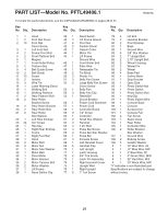
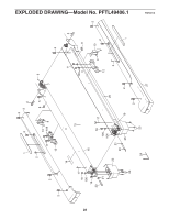
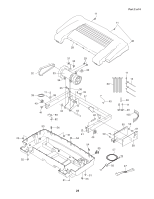
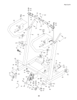
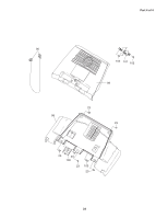
PART LIST-Model No. PFTL49406.1 R0507A To locate the parts listed below, see the EXPLODED DRAWING on pages 28 to 31. Key No. Qty. Description Key No. Qty. Description Key No. Qty. Description 1 1 Hood 1 2 Foot Rail Cover 2 10 Foot Rail Cover Screw 3 1 Left Foot Rail 4 2 Frame Pivot Bolt 5 2 Front Platform Bolt 6 1 Magnet 7 1 Front Roller/Pulley 8 2 Platform Nut 9 4 Belt Guide Screw 10 2 Belt Guide 11 13 Screw 12 2 Isolator 13 3 Wire Tie 14 1 Latch Warning Decal 15 1 Walking Belt 16 1 Walking Platform 17 2 Rear Platform Bolt 18 2 Rear Roller Bracket Screw 19 2 Rear Roller Bracket 20 2 Rear Roller Bolt 21 2 Rear Roller Star Washer 22 1 Left Rear Endcap 23 24 3/4" Screw 24 1 Hex Key 25 1 Right Rear Endcap 26 1 Frame 27 1 Right Foot Rail 28 1 Hood 29 2 Motor Bolt 30 2 Motor Nut 31 1 Motor Star Washer 32 1 Motor Belt 33 1 Drive Motor 34 1 Motor Bracket 35 2 Motor Tension Bolt 36 2 Motor Washer 37 1 Lift Frame 38 1 Reed Switch Clip 39 1 Reed Switch 78 4 Lift Bolt 40 2 Lift Frame Spacer 79 2 Handrail Bracket 41 6 Pivot Nut 80 2 Front Endcap 42 2 Caution Decal 81 1 Base 43 1 Hairpin Cotter 82 1 Ground Wire 44 1 Motor Pin 83 4 3/8" Star Washer 45 1 Lift Frame 84 2 1" Upright Bolt Ground Wire 85 2 2.75" Upright Bolt 46 1 Front Roller Bolt 86 2 Wheel Housing 47 1 Filter Wire 87 2 Wheel Pin 48 1 Releasable Tie 88 2 Wheel 49 2 Tie Block 89 4 Base Pad 50 3 Plastic Tie 90 1 Incline Motor 51 3 Belly Pan Screw 91 1 Stop Bracket 52 5 Large Belly Pan Screw/ 92 1 Optic Disk Cover Screw 93 1 Photo Switch Nut 53 1 Belly Pan 94 1 Photo Switch 54 3 Belly Pan Clip 95 1 Photo Switch Bolt 55 1 Reset/Off 96 1 Key/Clip Circuit Breaker 97 1 Photo Switch Wire 56 1 Power Cord Grommet 98 1 Console Base 57 1 Power Cord 99 1 Console 58 1 Controller Board 100 1 Access Door 59 9 1/2" Screw 101 1 Console Fan 60 1 Controller 102 2 Fan Screw 61 2 Small Star Washer 103 1 Static Decal 62 2 Handrail 104 1 Rear Roller 63 4 1.25" Bolt 105 1 Controller Wire 64 4 Pulse Bar Screw 106 2 Roller Bracket 65 4 Pulse Bar Star Washer Star Washer 66 1 Pulse Bar 107 1 Ground Wire 67 4 Console Screw 108 2 Endcap Screw 68 1 Left Handrail Cover 109 4 Isolator Washer 69 2 Handrail Cap # 1 12" Blue Wire, 2F 70 1 Left Upright # 1 12" Blue Wire, M/F 71 1 Latch Housing # 1 4" Blue Wire, 2F 72 2 3/4" Tek Screw # 1 4" Green Wire, M/R 73 1 Latch Pin Assembly # 1 22" Red Wire, M/F 74 1 Right Handrail Cover # 1 20" Black Wire, M/F 75 1 Upright Wire "#" indicates a non-illustrated part. 76 1 Right Upright Specifications are subject to change 77 6 1" Tek Screw without notice. 27
-
 1
1 -
2
-
3
-
4
-
5
-
6
-
7
-
8
-
9
-
10
-
11
-
12
-
13
-
14
-
15
-
16
-
17
-
18
-
19
-
20
-
21
-
 22
22 -
 23
23 -
 24
24 -
 25
25 -
 26
26 -
 27
27 -
 28
28 -
 29
29 -
 30
30 -
 31
31 -
 32
32
 |
 |
