ProForm 595 Canadian English Manual - Page 5
Assembly
 |
View all ProForm 595 manuals
Add to My Manuals
Save this manual to your list of manuals |
Page 5 highlights
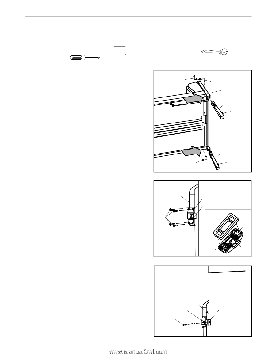
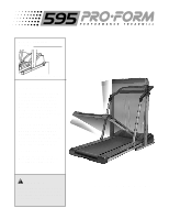
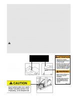
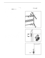
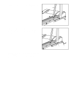
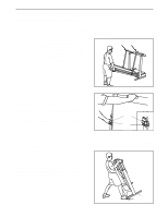
ASSEMBLY Assembly requires two people. Set the treadmill in a cleared area and remove the packing materials. Do not dispose of the packing materials until assembly is completed. Assembly requires the included allen wrench , and your own adjustable wrench phillips screwdriver . , and 1. Refer to the drawing on page 4 and identify the left 1 side of the treadmill. With the help of a second person, 92 carefully lay the treadmill on its left side. Firmly slide an Extension Leg (99) into each side of the Base (70) as shown. Make sure that the Extension Legs are turned so the Base Pads (89) are on the indicated sides. Using the included Allen Wrench (92), attach each Extension Leg with an Extension Screw (93). With the help of a second person, carefully raise the treadmill to the vertical position so both Extension Legs (99) are resting flat on the floor. 93 70 99 89 99 93 89 2. Remove the four Latch Screws (109) from the left 2 Upright (70). Without removing the tape from the Latch Bracket (60) 70 60, 66 and Latch Spacer (66), hold the Latch Spacer against 69 the left Upright (70) as shown. Attach the Latch Bracket and Latch Spacer with the four Latch Screws (109). Make sure that the Screws are tight, but do not 109 66 overtighten them; if the Screws are overtightened, 68 the Storage Latch (69) will not slide smoothly. Remove any tape that is still visible. Note: The inset drawing shows how the Latch Bracket (60), Latch Springs (68), Storage Latch (69), and Latch Spacer (66) fit together. 60 69 3. Remove the indicated Screw (4) from the treadmill Frame (1). Attach the plastic Catch (5) to the Frame with 3 the Screw. Note: It may be necessary to slide the Storage Latch (69) to the left while attaching the Catch. 1 69 5 4 5
-
 1
1 -
 2
2 -
 3
3 -
 4
4 -
 5
5 -
 6
6 -
 7
7 -
 8
8 -
 9
9 -
 10
10 -
 11
11 -
12
-
13
-
14
-
15
-
16
-
17
-
18
-
19
-
20
 |
 |