ProForm 675 Cardio Cross Trainer Elliptical English Manual - Page 6
Turn the Resistance Control 42 counterclockwise
 |
View all ProForm 675 Cardio Cross Trainer Elliptical manuals
Add to My Manuals
Save this manual to your list of manuals |
Page 6 highlights
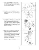
1. Identify the Front Stabilizer (10), which has round Endcaps (21) on its ends. While another person lifts the front of the Frame (1), attach the Front Stabilizer to the Frame with two M10 x 75mm Carriage Bolts (34) and two M10 Nylon Locknuts (33). 2. While another person lifts the back of the Frame (1), attach the Rear Stabilizer (9) to the Frame with two M10 x 75mm Carriage Bolts (34) and two M10 Nylon Locknuts (33). 3. The Console (23) requires four 1.5V "D" batteries; alkaline batteries are recommended. Remove the indicated screw from the battery drawer, and pull the battery drawer open. Insert four batteries into the battery drawer; make sure that the batteries are oriented as shown by the markings inside of the battery drawer. Close the battery drawer and reattach the screw. Note: When the batteries are installed correctly, the fan will turn on for a moment. 1 34 34 10 21 2 33 1 3 1 33 33 9 34 23 Batteries 4. While another person holds the Console (23) in the position shown, connect the console wire to the Extension Wire (68). Attach the Console (23) to the Upright (2) with the four Console Screws (59) included with the Console. Be careful to avoid pinching the wires. Attach the Water Bottle Holder (29) to the Upright (2) with two M4 x 22mm Screws (63). Turn the Resistance Control (42) counterclockwise to the lowest setting before continuing. Screw 4 Console Wire 59 2 23 68 42 29 63 6
-
 1
1 -
 2
2 -
 3
3 -
 4
4 -
 5
5 -
 6
6 -
 7
7 -
 8
8 -
 9
9 -
 10
10 -
 11
11 -
 12
12 -
13
-
14
-
15
-
16
 |
 |
