ProForm 675 Cardio Cross Trainer Elliptical English Manual - Page 7
pinched
 |
View all ProForm 675 Cardio Cross Trainer Elliptical manuals
Add to My Manuals
Save this manual to your list of manuals |
Page 7 highlights
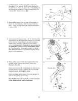
5. While another person holds the Upright (2) in the position shown, connect the Extension Wire (68) to the Reed Switch Wire (53). Next, connect the Resistance Cable (42) to the Lower Resistance Cable (43) in the following way: • See drawing A. Pull up on the metal bracket, and insert the tip of the Resistance Cable (42) into the wire clip on the Lower Resistance Cable (43) as shown. • See drawing B. Firmly pull the Resistance Cable (42) and slide it into the metal bracket on the Lower Resistance Cable (43) as shown. • See drawing C. Using pliers, squeeze the prongs on the upper end of the metal bracket together. Push the excess cable and wires down into the Frame (1). Slide the Upright (2) onto the Frame. Do not pinch the wires or cables. Attach the Upright to the Frame with two M10 x 74mm Button Bolts (7), two M10 Split Washers (45), and two M10 Nylon Locknuts (33). Do not tighten the Bolts yet. 6. Identify the Left Handlebar (6), which is marked with a sticker. Insert the Left Handlebar into one of the Handlebar Legs (5); make sure that the Handlebar Leg is turned so the hexagonal holes are on the indicated side. Attach the Left Handlebar to the Handlebar Leg with two M8 x 45mm Button Bolts (50) and two M8 Nylon Locknuts (38). Make sure that the Nylon Locknuts are inside of the hexagonal holes. Do not fully tighten the Button Bolts yet. Insert the Pivot Axle (26) into the Upright (2), and center the Pivot Axle. Apply a generous amount of the included grease to both ends of the Pivot Axle. Turn a Handlebar Spacer (47) so that the small arrow on the Handlebar Spacer is pointing toward the floor, and slide the Handlebar Spacer onto the post on the Left Handlebar (6). Next, slide the Left Handlebar onto the Pivot Axle (26). Slide a Handlebar Washer (55) and a Wave Washer (69) onto an M8 x 25mm Patch Screw (56), and tighten the Patch Screw into the Pivot Axle (26). Then, press the tabs on a Handlebar Cap (46) into the Handlebar Spacer (47). Assemble the Right Handlebar (8) and the other Handlebar Leg (5) in the same way. 5 33 42 43 1 2 Make sure the wires and cables 45 do not get 7 pinched and damaged during this step. 68 53 A Metal Bracket Control Cable 43 6 B C Control Cable 43 8 Grease 6 55 56 69 46 50 26 47 2 38 5 Hexagonal Holes 5 7
-
 1
1 -
 2
2 -
 3
3 -
 4
4 -
 5
5 -
 6
6 -
 7
7 -
 8
8 -
 9
9 -
 10
10 -
 11
11 -
 12
12 -
13
-
14
-
15
-
16
 |
 |
