ProForm 7.5c Owners Manual - Page 5
ProForm 7.5c Manual
 |
View all ProForm 7.5c manuals
Add to My Manuals
Save this manual to your list of manuals |
Page 5 highlights
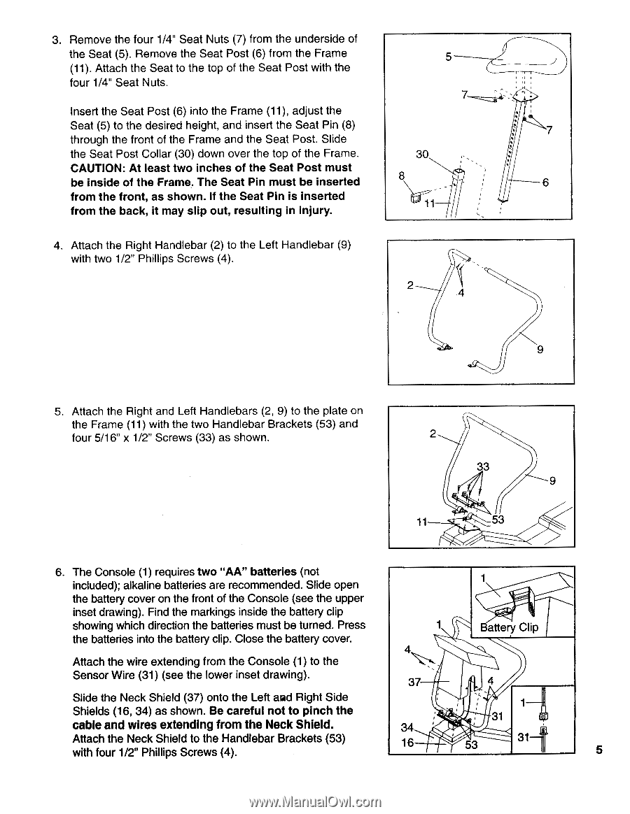
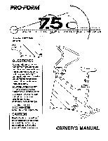
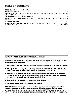
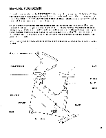
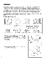
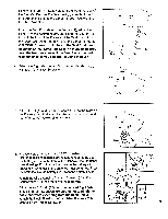
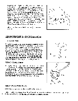
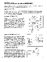
3. Remove the four 1/4" Seat Nuts (7) from the underside of the Seat (5). Remove the Seat Post (6) from the Frame 5 (11). Attach the Seat to the top of the Seat Post with the four 1/4" Seat Nuts. Insert the Seat Post (6) into the Frame (11), adjust the Seat (5) to the desired height, and insert the Seat Pin (8) 7 through the front of the Frame and the Seat Post. Slide the Seat Post Collar (30) down over the top of the Frame. 30 CAUTION: At least two inches of the Seat Post must be inside of the Frame. The Seat Pin must be inserted 8 6 from the front, as shown. If the Seat Pin is inserted from the back, it may slip out, resulting in injury. 11 4. Attach the Right Handlebar (2) to the Left Handlebar (9) with two 1/2" Phillips Screws (4). 2 4 9 5. Attach the Right and Left Handlebars (2, 9) to the plate on the Frame (11) with the two Handlebar Brackets (53) and four 5/16" x 1/2" Screws (33) as shown. 2 33 9 11 53 6. The Console (1) requires two "AA" batteries (not included); alkaline batteries are recommended. Slide open the battery cover on the front of the Console (see the upper inset drawing). Find the markings inside the battery clip showing which direction the batteries must be turned. Press the batteries into the battery clip. Close the battery cover. 4 Attach the wire extending from the Console (1) to the Battery C ip Sensor Wire (31) (see the lower inset drawing). 37 4 Slide the Neck Shield (37) onto the Left mad Right Side Shields (16, 34) as shown. Be careful not to pinch the cable and wires extending from the Neck Shield. 34 31 Attach the Neck Shield to the Handlebar Brackets (53) with four 1/2" Phillips Screws (4). 16 53 1 5
-
 1
1 -
 2
2 -
 3
3 -
 4
4 -
 5
5 -
 6
6 -
 7
7 -
 8
8 -
 9
9 -
 10
10 -
 11
11 -
12
 |
 |