ProForm 700 Gx Treadmill English Manual - Page 9
The Console May Be Damaged When
 |
View all ProForm 700 Gx Treadmill manuals
Add to My Manuals
Save this manual to your list of manuals |
Page 9 highlights
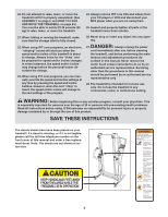
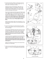
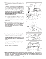
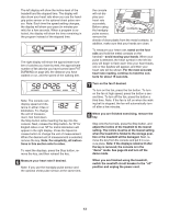
8. With the help of another person, hold the console assembly near the Right Upright (119) and the left Upright (not shown). Connect the Wire Harness (118) to the wire harness in the console assembly. Make sure to connect the connectors properly (see the inset drawing); the connectors should slide together easily and snap into place. If the connectors do not slide together easily and snap into place, turn one connector and try again. IF THE CONNECTORS ARE NOT CONNECTED PROPERLY, THE CONSOLE MAY BE DAMAGED WHEN THE POWER IS TURNED ON. Insert the excess wire harness back into the right Handrail (108). Set the console assembly on the Right Upright (119) and the Left Upright (not shown) so it fits over the small tabs on the Handrails (108).Thread two 1/4" x 1" Bolts (117) with 1/4" Star Washers (136) into each side of the console assembly. After you have started all four Bolts, tighten them. 9. Attach the Weight Rack (2) to the Left Upright (111) and the Right Upright (not shown) with four Rack Bolts (55) and four Rack Nuts (57). Note: Be sure to orient the Weight Rack with the bolt holes toward the indicated bend in the Uprights. 8 Console Assembly 118 108 Tab 9 55 Bend Right Handrail 136 117 119 111 2 57 10.Lower the Uprights (111, 119) until the Handrails (108) are touching the floor. Note: If necessary, pull out on the 10 latch knob so the pin does not hit the Frame (21). See the lower drawing. Position the Uprights (111, 119) 133 so that the treadmill Frame (21) is centered between the Uprights. Firmly tighten the four Upright Bolts (133). Then, raise the Uprights (111, 119) back to the vertical position. Note: If necessary, pull out on the latch knob so the pin does not hit the Frame (21). Place the Weights on the Weight Rack. 119 Latch 111, 119 Knob 21 108 111 21 11. Make sure that all parts are properly tightened before you use the treadmill. Note: Extra hardware may be included. Keep the included allen wrenches in a secure place; the large allen wrench is used to adjust the walking belt (see page 26). To protect the floor or carpet, place a mat under the treadmill. If there is a sheet of clear plastic on a decal, remove the plastic. 9
-
 1
1 -
2
-
3
-
 4
4 -
 5
5 -
 6
6 -
 7
7 -
 8
8 -
 9
9 -
 10
10 -
 11
11 -
 12
12 -
 13
13 -
 14
14 -
15
-
16
-
17
-
18
-
19
-
20
-
21
-
22
-
23
-
24
-
25
-
26
-
27
-
28
-
29
-
30
-
31
-
32
-
33
-
34
 |
 |
