ProForm 730cs English Manual - Page 23
Incline Leg Pivot Bolt - motor
 |
View all ProForm 730cs manuals
Add to My Manuals
Save this manual to your list of manuals |
Page 23 highlights
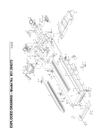
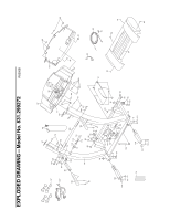
PART LISTÑModel No. 831.299272 R0200B To locate the parts listed below, refer to the EXPLODED DRAWING attached in the center of this manual. Key No. Qty. Description Key No. Qty. Description Key No. Qty. Description 11 21 34 4* 1 51 61 71 81 92 10** 1 11 1 12 1 13 1 14 1 15 8 16 4 17 4 18 2 19 1 20 2 21 1 22 1 23 1 24 1 25 1 26 1 27 1 28 1 29 1 30 8 31 1 32 2 33 2 34 1 35 1 36 3 37 2 38 4 39 4 40 1 41 2 42 1 43 1 Motor Belt 44 2 Platform Screw (mid) 91 1 Incline Motor Plate Pulley/Flywheel/Fan 45 2 Isolator 92 1 Right Foot Rail Cap Motor Nut 46 4 Isolator Screw 93 1 Motor Tension Spacer Motor/Pulley/ 47 15 Plastic Fastener 94 1 Motor Hood Flywheel/ Fan 48 1 Shield 95 2 Front Wheel Incline Motor Bolt 49 2 Belt Guide 96 1 Incline Motor Shield Plastic Incline Motor 50 1 Book Holder 97 4 Thick Base Pad Spacer 51 1 Front Belly Pan 98 1 12Ó Audio Wire Incline Motor 52 1 Power Supply 99 1 Upright Grommet Stop Bracket 53 4 Cable Tie Clamp 100 1 Allen Wrench Base Pad 54 4 Cable Tie 101 10 Base Pad Screw Hand Weight Set 55 1 Walking Belt 102 1 Lock Knob Rear Foot Spacer 56 1 24Ó Reed Harness 103 2 Extension Leg Frame 57 1 Rear Roller 104 2 Extension Leg Cap Optic Switch Bolt 58 1 Belly Pan Spacer 105 1 Shock Incline Motor Pivot Bolt 59 2 Rear Foot 106 1 Choke Incline Motor Nut 60 1 Rear Foot Screw 107 2 Pulse Bar Bolt Hood Screw 61 1 Ground Wire 108 2 Pulse Bar Washer Plastic Stand-Off 62 8 Ground Wire Screw 109 1 Pulse Bar Hood Bracket (short) 63 1 Belly Pan 110 2 Handrail Foam Grip Hood Bracket (long) 64 1 Rear Endcap 111 1 Lock Knob Sleeve Warning Decal 65 2 Rear Roller Adj. Bolt 112 1 Spring Reed Switch 66 1 Motor 113 1 Lock Pin Collar Reed Switch Clip 67 1 Latch Decal 114 1 Pin Clip Motor/Controller Wire 68 4 Platform Screw 115 1 Lock Pin Controller 69 8 Electronics Screw 116 1 Console Base Bottom Electronics Bracket 70 1 Latch Catch 117 2 Upright Endcap Circuit Breaker 71 1 Walking Platform 118** 1 Chest Pulse Sensor Power Cord 72 5 8Ó Cable Tie # 1 8Ó White Wire, 2F Power Cord Grommet 73 1 Jack # 1 4Ó White Wire, M/F On/Off Switch 74 1 Motor Tension Bolt # 1 9Ó Wire Harness Hood Bracket Screw/ 75 2 Foot Rail Insert # 1 8Ó Blue Wire, 2F Incline Shield Screw 76 10 Screw # 1 4Ó Blue Wire, 2F Incline Leg 77 1 Console # 1 4Ó Black Wire, 2F Frame Pivot Bolt 78 1 Metal Incline Spacer # 1 4Ó Green Wire, F/Ring Frame Pivot Spacer 79 4 Long Screw # 1 8Ó Green Wire, F/Ring Upright Wire Harness 80 1 10Õ I-Fit Wire # 1 8Ó Green Wire, 2 Ring Front Roller Adj. Bolt 81 4 Motor Star Washer # 1 User's Manual Roller Adj. Washer 82 1 Upright Motor Tension Nut/ 83 2 Incline Leg Pivot Bolt * Includes all parts shown in the Front Roller Nut 84 1 50Ó Wire Harness box Motor Bolt 85 2 Handrail Extension **For more information about the Cap Screw 86 2 Wheel Bolt optional hand weight set or chest Left Foot Rail Cap 87 1 Console Base pulse sensor, see page 18 Foot Rail 88 1 Motor Tension Washer # These parts are not illustrated Front Roller/Pulley 89 10 Console/Catch Screw Magnet 90 1 Key/Clip 23
-
 1
1 -
2
-
3
-
4
-
5
-
6
-
7
-
8
-
9
-
10
-
11
-
12
-
13
-
14
-
15
-
16
-
17
-
 18
18 -
 19
19 -
 20
20 -
 21
21 -
 22
22 -
 23
23 -
 24
24 -
 25
25 -
 26
26
 |
 |