ProForm 750 Treadmill English Manual - Page 7
Be Damaged When The Power Is Turned On. - console
 |
View all ProForm 750 Treadmill manuals
Add to My Manuals
Save this manual to your list of manuals |
Page 7 highlights
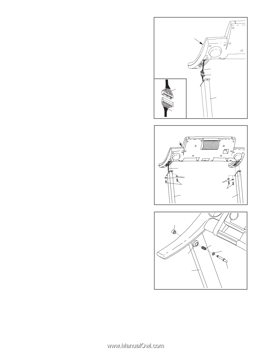
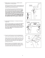
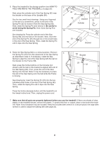
2. With the help of a second person, carefully raise the Uprights (84) to a vertical position. 2 Have the second person hold the console assembly near the Uprights (84). Look under the console assembly and locate the Console Wire Harness (78). Cut the plastic ties securing the Upright Wire Harness (77) to the right Upright (84). Next, connect the Upright Wire Harness to the Console Wire Harness (78). Make sure to connect the connectors properly (see the inset drawing). The connectors should slide together easily and snap into place. If they do not, turn one connector and then try again. IF THE CONNECTORS ARE NOT CONNECTED PROPERLY, THE CONSOLE MAY BE DAMAGED WHEN THE POWER IS TURNED ON. Console Assembly 78 77 3. Insert the Wire Harnesses (77, 78) down into the right Upright (84). Set the console assembly on the Uprights (84). Be careful to avoid pinching the Wire Harnesses (77, 78). While a second person holds the console assembly, attach it with four Console Bolts (64) and four Star Washers (8) as shown; start all four Console Bolts and then firmly tighten them. 3 Console Assembly 77, 78 8 64 84 4. Press the Latch Housing (73) into the left Upright (84). Tap the Latch Housing with a rubber mallet if necessary. Remove the knob from the pin. Make sure that the collar and the spring are on the pin. (Note: If there are two collars, place one on each side of the spring.) Next, insert the pin into the Latch Housing (73). Then, tighten the knob back onto the pin. Plug in the power cord as described on page 10, and then turn on the power as described on page 12. Note: The treadmill may automatically rise to the maximum incline level and then return to the minimum level. 4 Knob 73 84 78 77 84 8 64 84 Spring Collar Pin 7
-
 1
1 -
 2
2 -
 3
3 -
 4
4 -
 5
5 -
 6
6 -
 7
7 -
 8
8 -
 9
9 -
 10
10 -
 11
11 -
 12
12 -
13
-
14
-
15
-
16
-
17
-
18
-
19
-
20
-
21
-
22
-
23
-
24
-
25
-
26
-
27
-
28
-
29
-
30
 |
 |