ProForm 800 English Manual - Page 7
Attach the Front Leg 3 to the Bench Frame 5
 |
View all ProForm 800 manuals
Add to My Manuals
Save this manual to your list of manuals |
Page 7 highlights
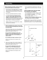
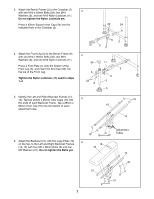
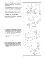
3. Attach the Bench Frame (5) to the Crossbar (2) 3 with two M10 x 60mm Bolts (29), two M10 Washers (6), and two M10 Nylon Locknuts (11). Do not tighten the Nylon Locknuts yet. Press a 45mm Square Inner Cap (24) into the indicated hole in the Crossbar (2). 29 24 4. Attach the Front Leg (3) to the Bench Frame (5) with two M10 x 90mm Bolts (23), two M10 Washers (6), and two M10 Nylon Locknuts (11). Press a Foot Plate (4) onto the bottom of the Front Leg (3), and insert the End Cap (30) into the top of the Front Leg. Tighten the Nylon Locknuts (11) used in steps 1Ð4. 62 5 11 4 30 6 23 6 11 5 11 3 4 5. Identify the Left and Right Backrest Frames (14, 15). Tap two 25mm x 25mm Inner Caps (10) into 5 the ends of each Backrest Frame. Tap a 25mm x 50mm Inner Cap (16) into the bottom of each adjustment tube. 10 15 14 6. Attach the Backrest (12), with the Logo Plate (13) on the top, to the Left and Right Backrest Frames (14, 15) with four M6 x 38mm Bolts (9) and four M6 Washers (31). Do not tighten the Bolts yet. 10 16 6 13 12 15 9 7 Adjustment Tubes 14 31 9 31
-
 1
1 -
 2
2 -
 3
3 -
 4
4 -
 5
5 -
 6
6 -
 7
7 -
 8
8 -
 9
9 -
 10
10 -
 11
11 -
 12
12 -
13
-
14
-
15
-
16
-
17
-
18
-
19
 |
 |
